Installing the Contact Closure Module
Overview
The Phoenix A8930C contact closure module is capable of supporting up to
8 contact closure inputs, and 8 contact closure outputs per module. With up to 4 modules available per system, up to 32 contact inputs and outputs can be transmitted. Contact closure modules are color coded black, and can be installed in slots 15, 16, 17, or 18. The input/output interface is four, ganged RJ45 connectors located on each card, See contact closure
Tools and materials required
The contact closure modules are held in place with simple thumbscrews with screwdriver slots. The only tool recommended is a small flat blade screwdriver.
Installation instructions:
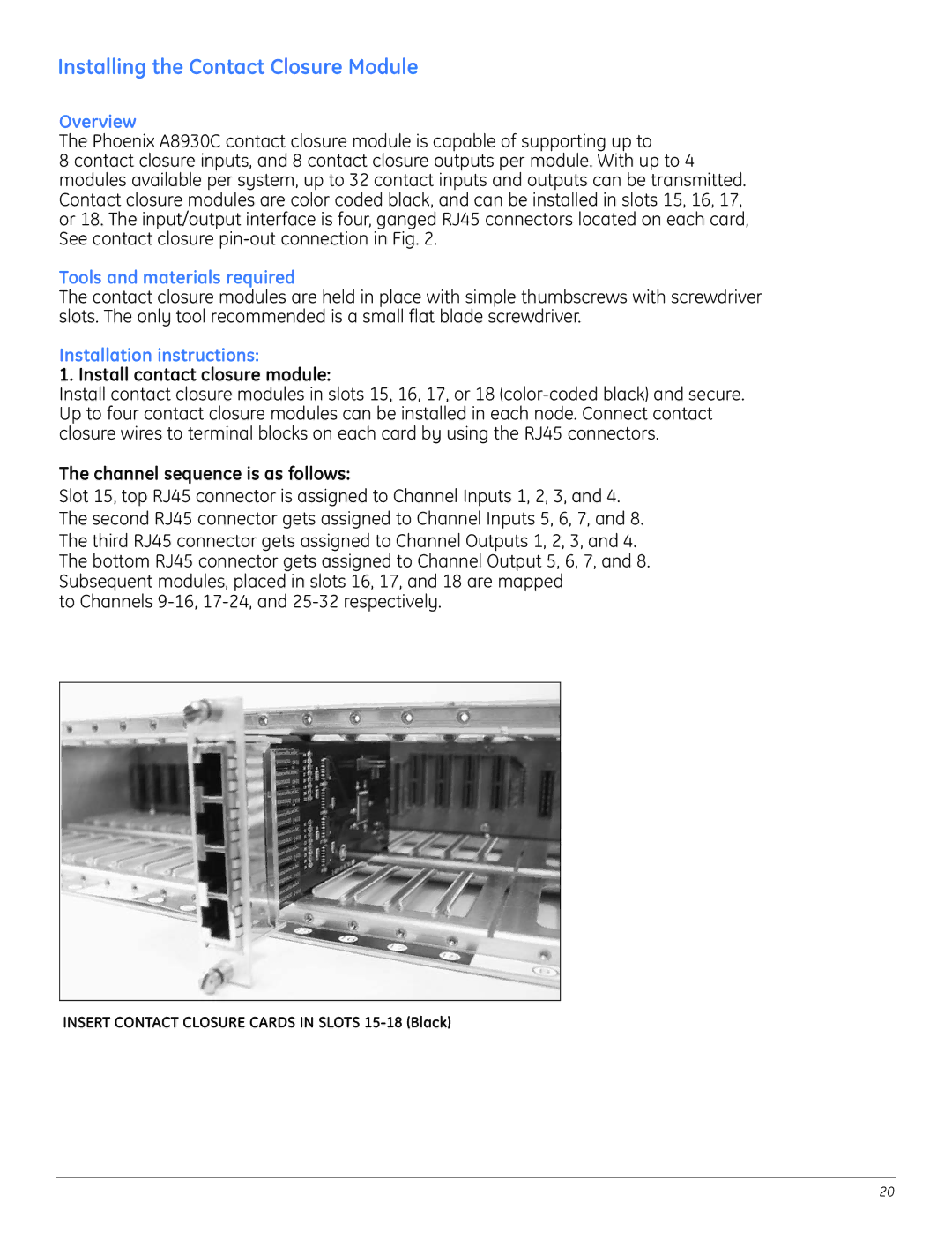
1. Install contact closure module:
Install contact closure modules in slots 15, 16, 17, or 18
The channel sequence is as follows:
Slot 15, top RJ45 connector is assigned to Channel Inputs 1, 2, 3, and 4. The second RJ45 connector gets assigned to Channel Inputs 5, 6, 7, and 8. The third RJ45 connector gets assigned to Channel Outputs 1, 2, 3, and 4. The bottom RJ45 connector gets assigned to Channel Output 5, 6, 7, and 8. Subsequent modules, placed in slots 16, 17, and 18 are mapped
to Channels
INSERT CONTACT CLOSURE CARDS IN SLOTS
20