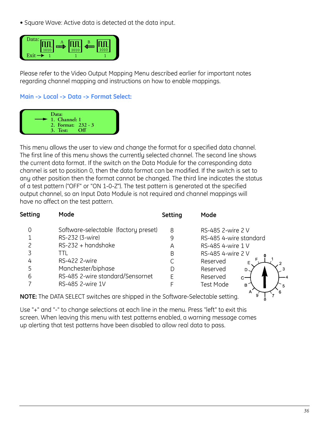
• Square Wave: Active data is detected at the data input.
Data:
1010
Exit ![]() 1
1
A
1010
1
B
1010
1
Please refer to the Video Output Mapping Menu described earlier for important notes regarding channel mapping and instructions on how to enable mappings.
Main -> Local -> Data -> Format Select:
Data:
![]() 1. Channel: 1
1. Channel: 1
2.Format: 232 - 3
3.Test: Off
This menu allows the user to view and change the format for a specified data channel. The first line of this menu shows the currently selected channel. The second line shows the current data format. If the switch on the Data Module for the corresponding data channel is set to position 0, then the data format can be modified. If the switch is set to any other position then the format cannot be changed. The third line indicates the status of a test pattern ("OFF" or "ON
Setting | Mode | Setting | Mode |
0 | 8 | ||
1 | 9 | ||
2 | A | ||
3 | TTL | B | |
4 | C | Reserved | |
5 | Manchester/biphase | D | Reserved |
6 | E | Reserved | |
7 | F | Test Mode |
NOTE: The DATA SELECT switches are shipped in the
Use "+" and
36