Installing the Data Module
Overview
The Phoenix A8910MPD data module is capable of inserting/extracting
4 channels of multiprotocol serial data (MPD) per module. With a maximum of four cards per node, the system capacity is 16 channels. Each channel is capable of transmitting and receiving serial data throughout the Phoenix system. The card is not limited to any single data type so that various formats can be mixed on a single card. As with other GE Security MPD products, data translation capabilities are included.
Tools and materials required
The data modules are held in place with simple thumbscrews with screwdriver slots. The only tool recommended is a small flat blade screwdriver.
Installation instructions:
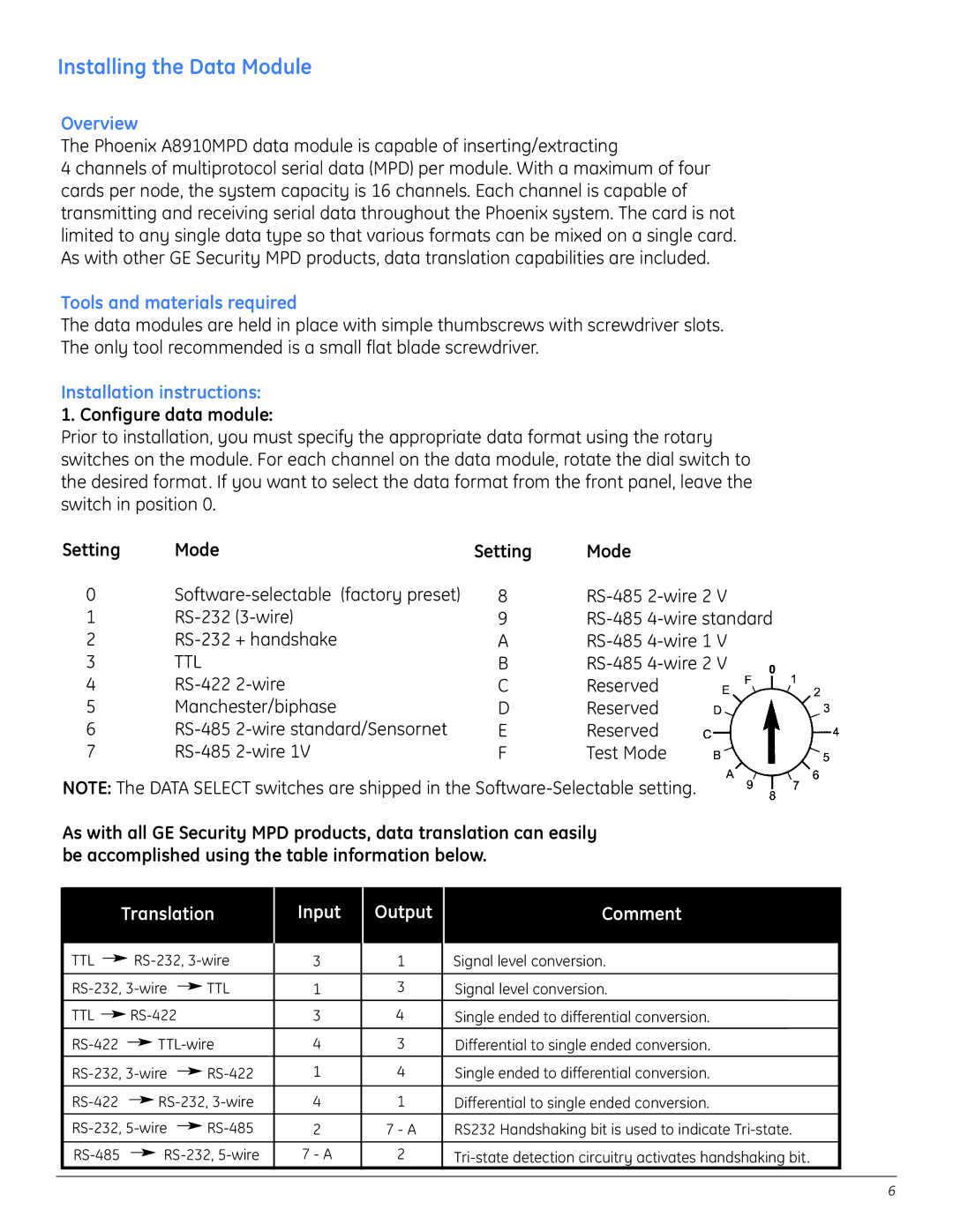
1. Configure data module:
Prior to installation, you must specify the appropriate data format using the rotary switches on the module. For each channel on the data module, rotate the dial switch to the desired format. If you want to select the data format from the front panel, leave the switch in position 0.
Setting | Mode | Setting | Mode |
0 | 8 | ||
1 | 9 | ||
2 | A | ||
3 | TTL | B | |
4 | C | Reserved | |
5 | Manchester/biphase | D | Reserved |
6 | E | Reserved | |
7 | F | Test Mode |
NOTE: The DATA SELECT switches are shipped in the
As with all GE Security MPD products, data translation can easily be accomplished using the table information below.
Translation
Input
Output
Comment
|
| TTL |
|
|
|
|
| 3 | 1 | Signal level conversion. |
| |||||||
|
|
|
|
| ||||||||||||||
|
|
|
|
|
|
|
|
|
|
|
|
|
|
|
|
|
| |
|
|
| TTL | 1 | 3 | Signal level conversion. |
| |||||||||||
|
|
|
| |||||||||||||||
|
|
|
|
|
|
|
|
|
|
|
|
|
|
|
|
|
|
|
|
| TTL |
|
|
|
|
| 3 | 4 | Single ended to differential conversion. |
| |||||||
|
|
|
|
|
|
| ||||||||||||
|
|
|
|
|
|
|
|
|
|
|
|
|
|
|
|
|
| |
|
|
|
|
|
|
| 4 | 3 | Differential to single ended conversion. |
| ||||||||
|
|
|
|
|
| |||||||||||||
|
|
|
|
|
|
|
|
|
|
|
|
|
|
|
|
|
| |
|
|
| 1 | 4 | Single ended to differential conversion. |
| ||||||||||||
|
|
|
| |||||||||||||||
|
|
|
|
|
|
|
|
|
|
|
|
|
|
|
|
|
| |
|
|
|
|
|
|
| 4 | 1 | Differential to single ended conversion. |
| ||||||||
|
|
|
|
|
|
| ||||||||||||
|
|
| 2 | 7 - A | RS232 Handshaking bit is used to indicate |
| ||||||||||||
|
|
|
| |||||||||||||||
|
|
|
|
|
|
|
|
|
|
|
|
|
|
|
|
|
| |
|
|
|
|
|
|
| 7 - A | 2 |
| |||||||||
|
|
|
|
|
|
|
| |||||||||||
|
|
|
|
|
|
|
|
|
|
|
|
|
|
|
|
|
|
|
6