Main -> Local -> Audio:
Audio Menu
![]() 1. Input Mapping
1. Input Mapping
2.Output Mapping
3.Test Select
Audio Input and Audio Output mapping and tests can be accessed from the
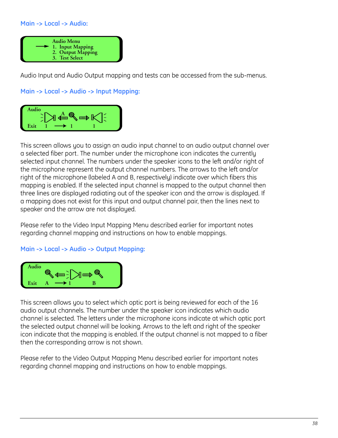
Main -> Local -> Audio -> Input Mapping:
Audio
| A |
|
Exit 1 | 1 | 1 |
This screen allows you to assign an audio input channel to an audio output channel over a selected fiber port. The number under the microphone icon indicates the currently selected input channel. The numbers under the speaker icons to the left and/or right of the microphone represent the output channel numbers. The arrows to the left and/or right of the microphone (labeled A and B, respectively) indicate over which fibers this mapping is enabled. If the selected input channel is mapped to the output channel then three lines are displayed radiating out of the speaker icon and the arrow is displayed. If a mapping does not exist for this input and output channel pair, then the lines next to speaker and the arrow are not displayed.
Please refer to the Video Input Mapping Menu described earlier for important notes regarding channel mapping and instructions on how to enable mappings.
Main -> Local -> Audio -> Output Mapping:
Audio |
|
|
Exit A | 1 | B |
This screen allows you to select which optic port is being reviewed for each of the 16 audio output channels. The number under the speaker icon indicates which audio channel is selected. The letters under the microphone icons indicate at which optic port the selected output channel will be looking. Arrows to the left and right of the speaker icon indicate that the mapping is enabled. If the output channel is not mapped to a fiber then the corresponding arrow is not shown.
Please refer to the Video Output Mapping Menu described earlier for important notes regarding channel mapping and instructions on how to enable mappings.
38