Installing the Optical Transceiver Module
Overview
The Phoenix optical transceiver module is used to provide connectivity to the fiber connections between nodes. The A8972FLC optical transceiver module contains a single optical transceiver with dual LC connectors and is used as an ‘end node’ in either a point to point, or linear system. The A8974FLC optical transceiver module features two optical transceivers with two dual LC connectors and is used in repeating nodes within a linear system as well as all nodes in a
Tools and materials required
The optical module is held in place with simple thumbscrews with screwdriver slots. The only tool recommended is a small flat blade screwdriver.
* WARNING:
Insure main power is off when installing or removing.
Installation instructions:
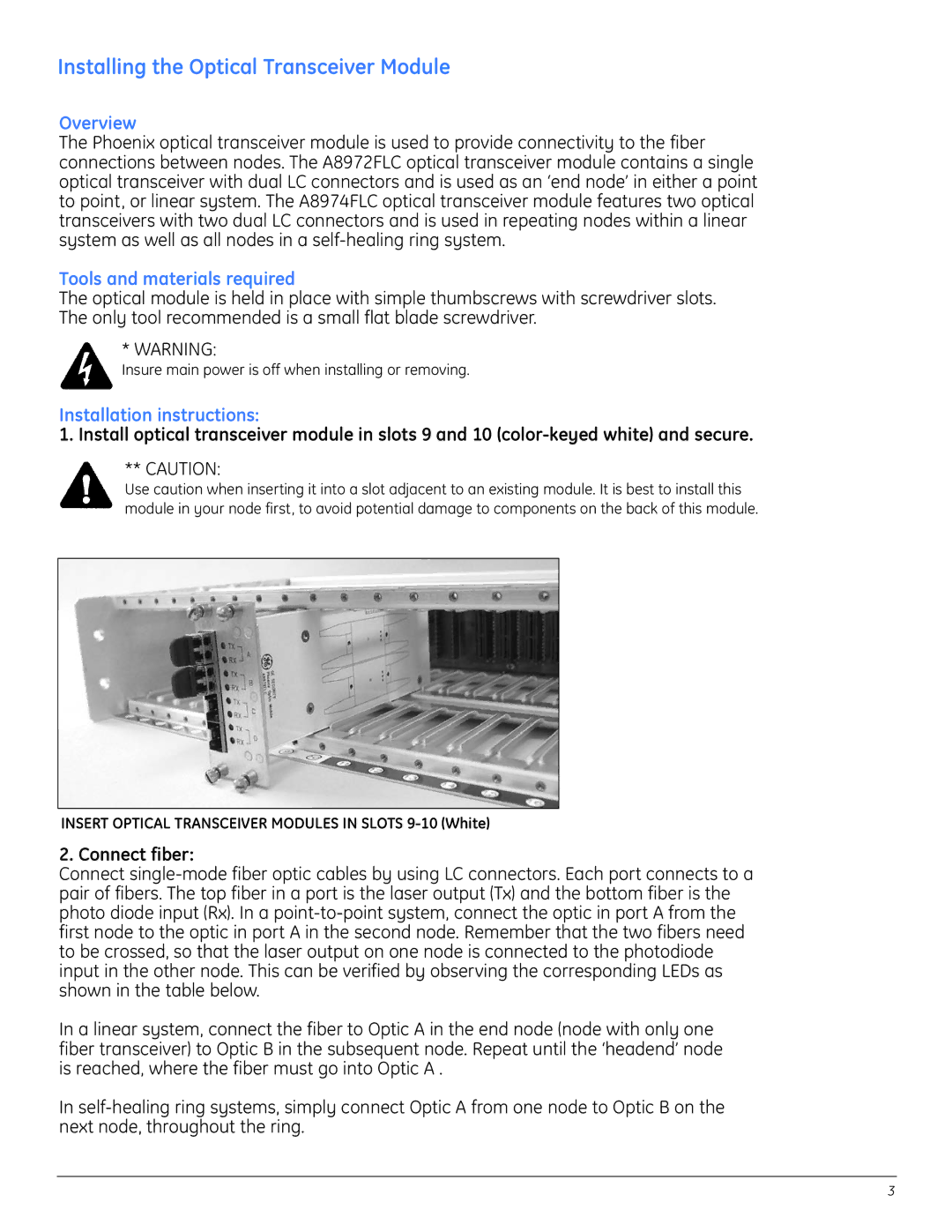
1. Install optical transceiver module in slots 9 and 10
** CAUTION:
Use caution when inserting it into a slot adjacent to an existing module. It is best to install this module in your node first, to avoid potential damage to components on the back of this module.
INSERT OPTICAL TRANSCEIVER MODULES IN SLOTS
2. Connect fiber:
Connect
In a linear system, connect the fiber to Optic A in the end node (node with only one fiber transceiver) to Optic B in the subsequent node. Repeat until the ‘headend’ node is reached, where the fiber must go into Optic A .
In
3