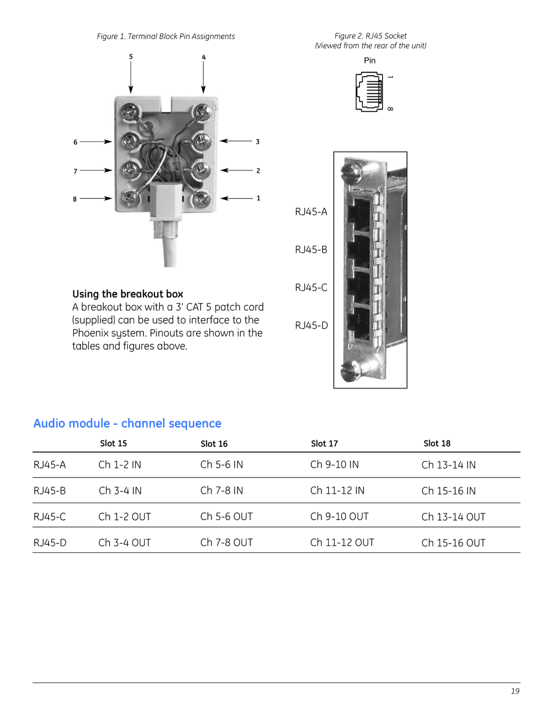
Figure 1. Terminal Block Pin Assignments
54
6 |
|
|
|
|
| 3 | ||
|
|
|
| |||||
7 |
|
|
|
| 2 | |||
|
| |||||||
8 |
|
|
|
| 1 | |||
|
| |||||||
Using the breakout box
A breakout box with a 3’ CAT 5 patch cord (supplied) can be used to interface to the Phoenix system. Pinouts are shown in the tables and figures above.
Figure 2. RJ45 Socket
(Viewed from the rear of the unit)
Pin
1 8
Audio module - channel sequence
| Slot 15 | Slot 16 | Slot 17 | Slot 18 |
Ch | Ch | Ch | Ch | |
|
|
|
|
|
Ch | Ch | Ch | Ch | |
|
|
|
|
|
Ch | Ch | Ch | Ch | |
|
|
|
|
|
Ch | Ch | Ch | Ch | |
|
|
|
|
|
19