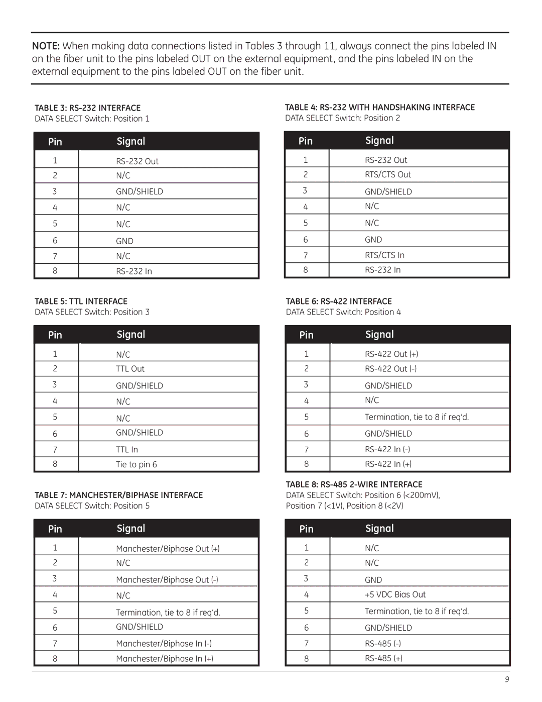
NOTE: When making data connections listed in Tables 3 through 11, always connect the pins labeled IN on the fiber unit to the pins labeled OUT on the external equipment, and the pins labeled IN on the external equipment to the pins labeled OUT on the fiber unit.
TABLE 3:
DATA SELECT Switch: Position 1
Pin | Signal |
1 | |
|
|
2 | N/C |
|
|
3 | GND/SHIELD |
|
|
4 | N/C |
|
|
5 | N/C |
|
|
6 | GND |
|
|
7 | N/C |
|
|
8 |
TABLE 5: TTL INTERFACE
DATA SELECT Switch: Position 3
Pin | Signal |
1 | N/C |
|
|
2 | TTL Out |
|
|
3 | GND/SHIELD |
4 | N/C |
5 | N/C |
|
|
6 | GND/SHIELD |
|
|
7 | TTL In |
|
|
8 | Tie to pin 6 |
|
|
TABLE 7: MANCHESTER/BIPHASE INTERFACE
DATA SELECT Switch: Position 5
Pin | Signal |
1 | Manchester/Biphase Out (+) |
2 | N/C |
|
|
3 | Manchester/Biphase Out |
4 | N/C |
5 | Termination, tie to 8 if req’d. |
6 | GND/SHIELD |
|
|
7 | Manchester/Biphase In |
|
|
8 | Manchester/Biphase In (+) |
|
|
TABLE 4:
DATA SELECT Switch: Position 2
Pin | Signal |
1 | |
|
|
2 | RTS/CTS Out |
|
|
3 | GND/SHIELD |
4 | N/C |
|
|
5 | N/C |
|
|
6 | GND |
|
|
7 | RTS/CTS In |
|
|
8 | |
|
|
TABLE 6:
DATA SELECT Switch: Position 4
Pin | Signal | |
1 | ||
|
|
|
2 | Out | |
|
| |
3 | GND/SHIELD | |
4 | N/C |
|
|
| |
5 | Termination, tie to 8 if req’d. | |
|
| |
6 | GND/SHIELD | |
|
|
|
7 | In | |
|
|
|
8 | In (+) | |
|
|
|
TABLE 8:
DATA SELECT Switch: Position 6 (<200mV),
Position 7 (<1V), Position 8 (<2V)
Pin | Signal |
1 | N/C |
|
|
2 | N/C |
|
|
3 | GND |
4 | +5 VDC Bias Out |
|
|
5 | Termination, tie to 8 if req’d. |
|
|
6 | GND/SHIELD |
|
|
7 | |
|
|
8 | |
|
|
9