Installing the Video Module
Overview
The Phoenix A8900VI input module is capable of inserting up to four baseband, composite video signals per card. A maximum of four cards can be installed in any node, allowing up to 16 inputs per node.
The Phoenix A8905VO output module is capable of outputting up to 4 base band, composite video signals per card. A maximum of four cards can be installed in any node, allowing up to 16 outputs per node.
Tools and materials required
The video modules are held in place with simple thumbscrews with screwdriver slots. The only tool recommended is a small flat blade screwdriver.
Installation instructions:
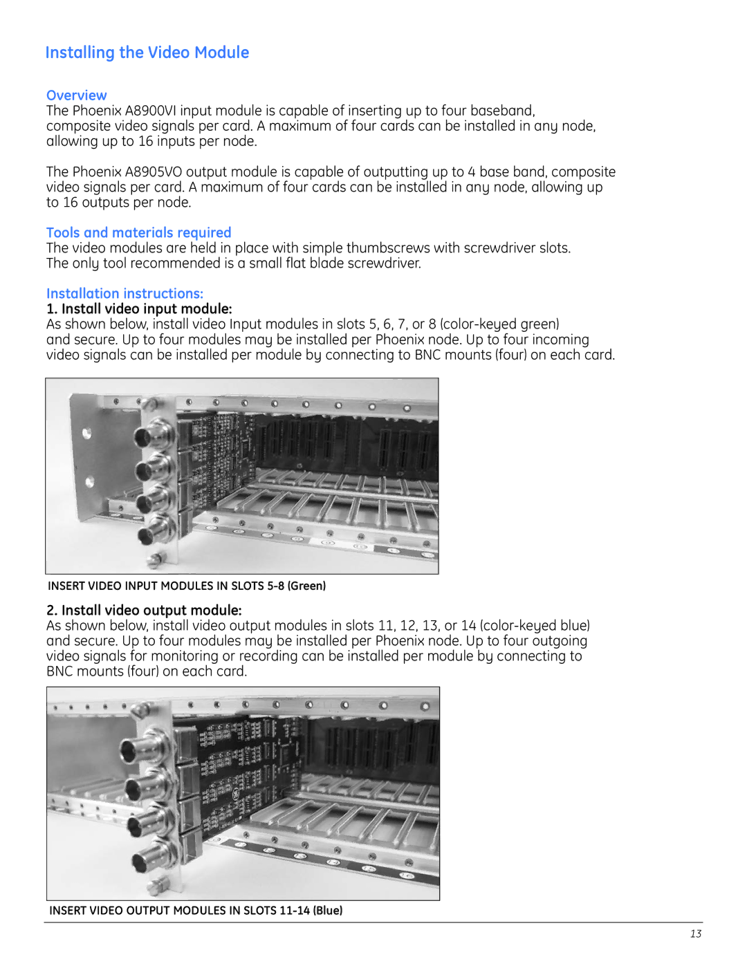
1. Install video input module:
As shown below, install video Input modules in slots 5, 6, 7, or 8
INSERT VIDEO INPUT MODULES IN SLOTS
2. Install video output module:
As shown below, install video output modules in slots 11, 12, 13, or 14
INSERT VIDEO OUTPUT MODULES IN SLOTS
13