DCP200 specifications
The Honeywell DCP200 is an advanced distributed control platform designed to enhance efficiency, reliability, and flexibility in industrial automation. With a robust architecture capable of supporting a wide range of applications, the DCP200 is perfect for sectors including oil and gas, chemical processing, power generation, and manufacturing.One of the key features of the Honeywell DCP200 is its scalability. It can be easily expanded to accommodate increasing demands, making it suitable for both small operations and large enterprises. This flexibility allows industries to adopt the system gradually, integrating it into their existing processes without substantial downtime or a steep learning curve.
The DCP200 is built on open standards, facilitating seamless integration with third-party systems and equipment. This compatibility ensures that companies can leverage existing infrastructures and investments, fostering a more cohesive operational environment. Enhanced interoperability is achieved via industry-standard communication protocols, enabling devices to communicate fluently across diverse platforms.
Another significant characteristic of the DCP200 is its powerful data acquisition and processing capabilities. The system utilizes state-of-the-art data analytics tools to monitor real-time information, enabling better decision-making and predictive maintenance. This proactive approach helps in reducing downtime, optimizing performance, and ultimately driving operational excellence.
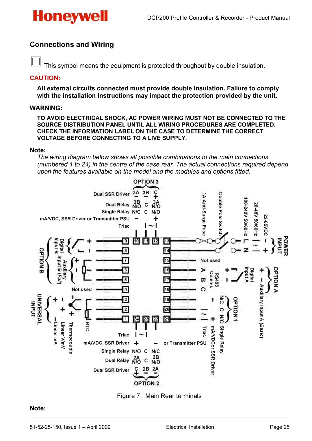
The DCP200 system supports a wide range of input and output options, ensuring it can interface with various sensors, actuators, and control devices. This adaptability contributes to its function as a central hub for industrial monitoring and control, enhancing data visibility and operational responsiveness.
Security is a top priority for Honeywell, and the DCP200 employs robust cybersecurity measures to protect critical infrastructure. The system includes advanced authentication protocols and data encryption techniques, safeguarding sensitive information from unauthorized access and potential cyber threats.
User experience is also a focal point of the DCP200. The platform features an intuitive graphical user interface that simplifies navigation and enhances operator engagement. Customizable dashboards provide at-a-glance insights into system performance, aiding both operators and management in identifying areas for improvement.
In conclusion, the Honeywell DCP200 is an innovative distributed control platform that marries flexibility, scalability, and security. With its comprehensive feature set and commitment to seamless integration, it stands as a vital tool for companies aiming to enhance their automation efforts and drive operational success in an increasingly complex industrial landscape.

