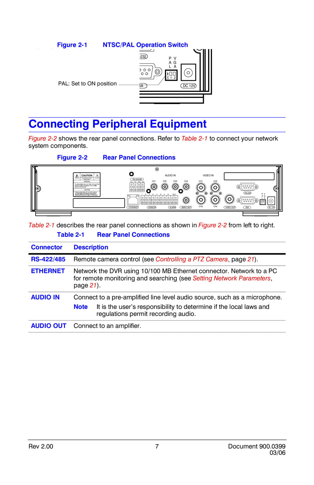
Figure 2-1 NTSC/PAL Operation Switch
CH3 PAL: CH4Set to ON position
VIDEO OUT
P V | ||
| A G | |
| L | A |
| ON 1 2 | |
VGA |
| DC 12V |
Connecting Peripheral Equipment
Figure 2-2 shows the rear panel connections. Refer to Table 2-1 to connect your network system components.
Figure 2-2 Rear Panel Connections
CAUTION |
|
| AUDIO IN |
|
| VIDEO IN | |
RISK OF ELECTRIC SHOCK |
|
|
|
|
|
| |
DO NOT OPEN | CH1 | CH2 | CH3 | CH4 | CH1 | CH2 | |
WARNING | TX+ TX- RX+ RX- | ||||||
TO REDUCETHE RISK OF FIRE OR ELECTRIC
SHOCK DOOTN EXPOSETHIS APPLIANCETO
RAIN OR MOISTURE
CAUTION |
|
|
|
|
|
|
|
|
TO REDUCETHE RISK OF ELECTRIC SHOCK |
|
|
|
|
|
|
| |
NO USER SERVICEABLEPARTS INSIDE.REFER | 1 G 2 G 3 | G 4 G | OUT |
|
|
|
| |
SERVICINGTO QUALIFIED SERVICE PERSONNEL |
|
|
|
|
| |||
|
|
|
|
|
|
|
| ON |
ETHERNET | SENSOR |
| ALARM | AUDIO OUT | CH3 | CH4 | VIDEO OUT | VGA |
|
|
|
PV A G L A
1 2
DC 12V
Table
Table 2-1 Rear Panel Connections
Connector Description
ETHERNET Network the DVR using 10/100 MB Ethernet connector. Network to a PC for remote monitoring and searching (see Setting Network Parameters, page 21).
AUDIO IN Connect to a
Note It is the user’s responsibility to determine if the local laws and regulations permit recording audio.
AUDIO OUT Connect to an amplifier.
Rev 2.00 | 7 | Document 900.0399 |
|
| 03/06 |