Table 2-1 Rear Panel Connections (Cont’d)
Connector Description
SENSOR IN Connect to external alarm sensor devices to signal the DVR to react to events. Four sensors can be connected to the equipment sensor
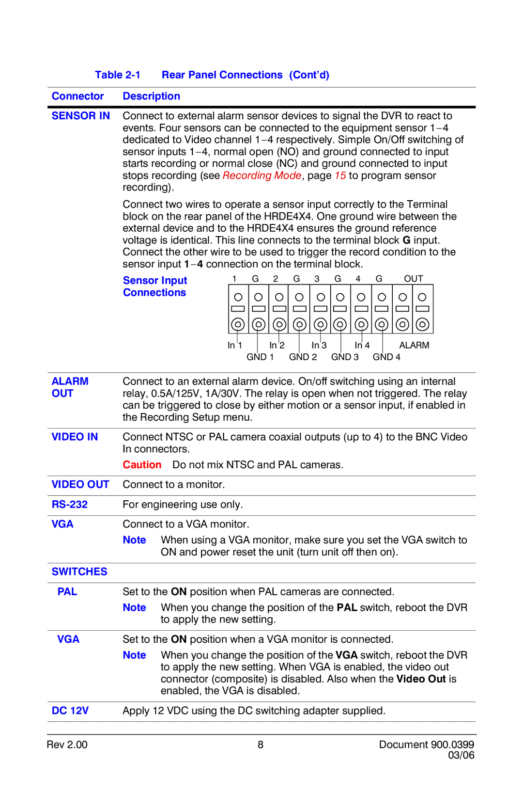
Connect two wires to operate a sensor input correctly to the Terminal block on the rear panel of the HRDE4X4. One ground wire between the external device and to the HRDE4X4 ensures the ground reference voltage is identical. This line connects to the terminal block G input. Connect the other wire to be used to trigger the record condition to the sensor input
Sensor Input | 1 G 2 G 3 G 4 G | OUT |
Connections |
|
|
In 1
In 2
In 3
In 4
ALARM
| GND 1 GND 2 GND 3 | GND 4 |
|
| |
ALARM | Connect to an external alarm device. On/off switching using an internal | |
OUT | relay, 0.5A/125V, 1A/30V. The relay is open when not triggered. The relay | |
| can be triggered to close by either motion or a sensor input, if enabled in | |
| the Recording Setup menu. |
|
|
| |
VIDEO IN | Connect NTSC or PAL camera coaxial outputs (up to 4) to the BNC Video | |
| In connectors. |
|
| Caution Do not mix NTSC and PAL cameras. |
|
|
|
|
VIDEO OUT | Connect to a monitor. |
|
|
|
|
For engineering use only. |
| |
|
|
|
VGA | Connect to a VGA monitor. |
|
| Note When using a VGA monitor, make sure you set the VGA switch to | |
| ON and power reset the unit (turn unit off then on). | |
|
|
|
SWITCHES |
|
|
|
| |
PAL | Set to the ON position when PAL cameras are connected. | |
| Note When you change the position of the PAL switch, reboot the DVR | |
| to apply the new setting. |
|
|
| |
VGA | Set to the ON position when a VGA monitor is connected. | |
| Note When you change the position of the VGA switch, reboot the DVR | |
| to apply the new setting. When VGA is enabled, the video out | |
| connector (composite) is disabled. Also when the Video Out is | |
| enabled, the VGA is disabled. |
|
|
| |
DC 12V | Apply 12 VDC using the DC switching adapter supplied. | |
|
|
|
|
|
|
Rev 2.00 | 8 | Document 900.0399 |
|
| 03/06 |