4.Route and secure the cable by attaching the cable clamp to the transom; drill one 9/64" diameter x 5/8" deep hole, then fill hole with
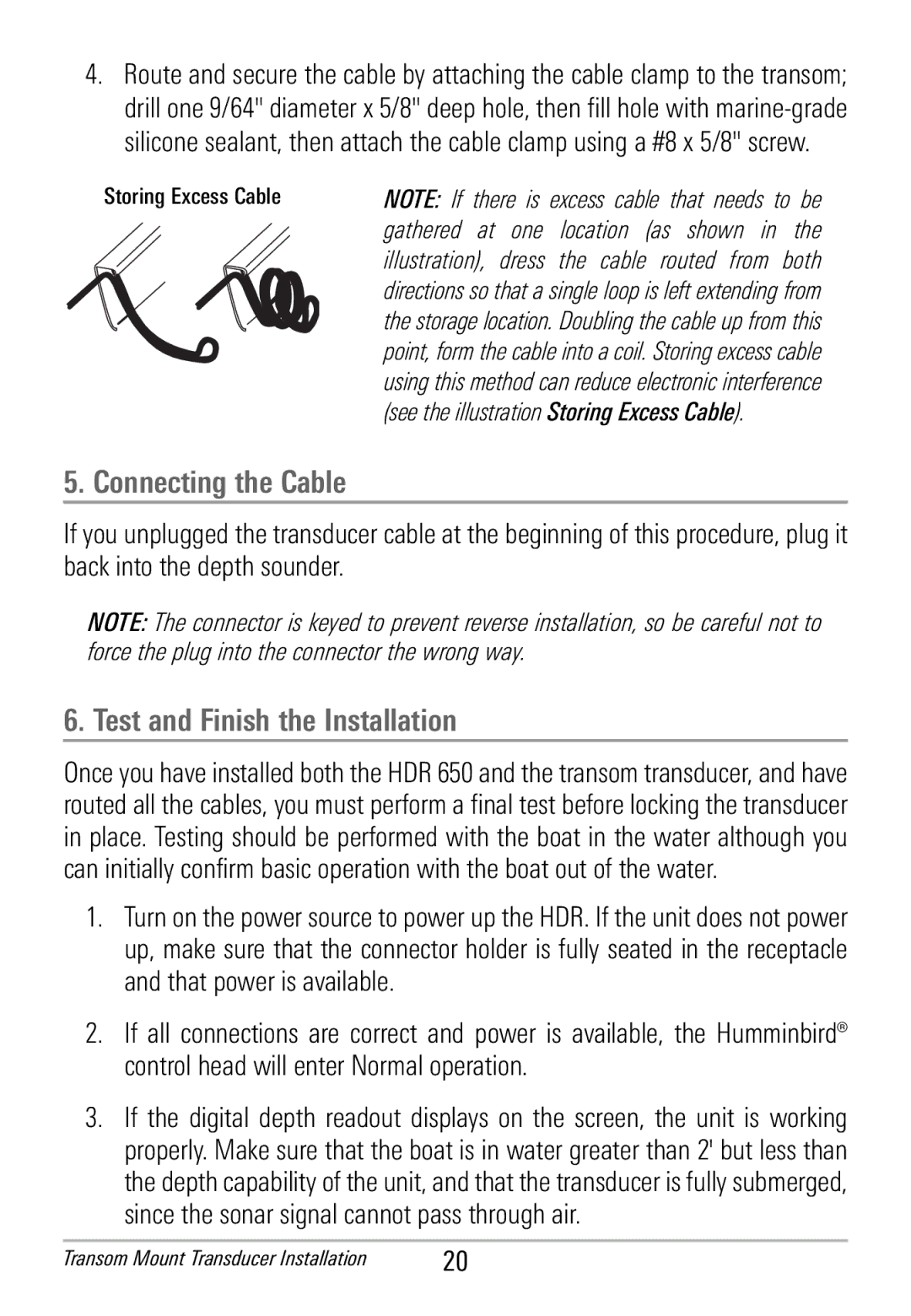
Storing Excess Cable | NOTE: If there is excess cable that needs to be |
| gathered at one location (as shown in the |
| illustration), dress the cable routed from both |
| directions so that a single loop is left extending from |
| the storage location. Doubling the cable up from this |
| point, form the cable into a coil. Storing excess cable |
| using this method can reduce electronic interference |
| (see the illustration Storing Excess Cable). |
5. Connecting the Cable
If you unplugged the transducercable at the beginningof this procedure, plug it back into the depth sounder.
NOTE: The connector is keyed to prevent reverse installation, so be careful not to force the plug into the connector the wrong way.
6. Test and Finish the Installation
Once you have installed both the HDR 650 and the transom transducer,and have routed all the cables, you must perform a final test before locking the transducer in place. Testing should be performed with the boat in the water although you can initially confirm basic operation with the boat out of the water.
1.Turnon the power source to power up the HDR. If the unit does not power up, make sure that the connector holder is fully seated in the receptacle and that power is available.
2.If all connections are correct and power is available, the Humminbird® control head will enter Normal operation.
3.If the digital depth readout displays on the screen, the unit is working properly. Make sure that the boat is in water greater than 2' but less than the depth capability of the unit, and that the transduceris fully submerged, since the sonar signal cannot pass through air.
Transom Mount Transducer Installation | 20 |