Maintenance
FU3 10 A Red | Control circuit (max. 10A). |
If FU3 blows the entire machine will be dead.
The circuit fuses are located on the circuit board under a cover on the control panel’s
FU1 | 10 | A Red | Power |
FU2 | 10 | A Red | Solenoid valves hydraulic system |
FU4 | 10 | A Red | Indicators, signal, hazard warning lights |
FU5 | 10 | A Red | Extra voltage outlet 2 |
FU6 | 20 | A Yellow | Cooling fan |
FU7 | 10 | A Red | Extra voltage outlet 1 |
FU8 | 20 | A Yellow | Starter motor engagement |
FU9 | 10 | A Red | Headlight |
FU10 | 7,5 A Brown | Lighting traffic kit | |
FU11 | 10 | A Red | Power outlet 12 V |
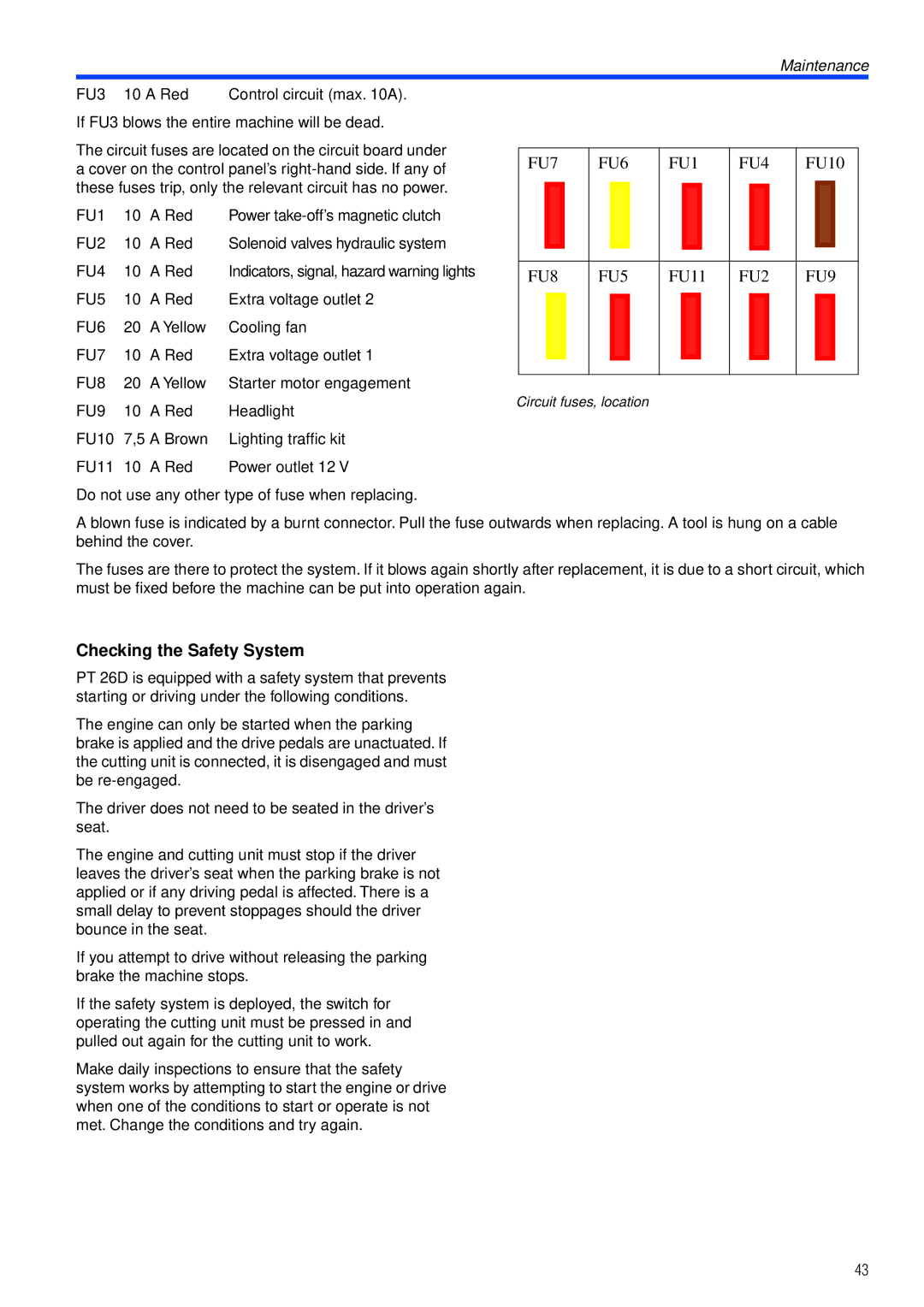
FU7 | FU6 | FU1 | FU4 | FU10 | ||||||||||||||||
|
|
|
|
|
|
|
|
|
|
|
|
|
|
|
|
|
|
|
|
|
|
|
|
|
|
|
|
|
|
|
|
|
|
|
|
|
|
|
|
|
|
|
|
|
|
|
|
|
|
|
|
|
|
|
|
|
|
|
|
|
|
|
|
|
|
|
|
|
|
|
|
|
|
|
|
|
|
|
|
|
|
|
|
|
|
|
|
|
|
|
|
|
|
|
|
|
|
|
|
|
|
|
|
|
FU8 | FU5 | FU11 | FU2 | FU9 | ||||||||||||||||
|
|
|
|
|
|
|
|
|
|
|
|
|
|
|
|
|
|
|
|
|
|
|
|
|
|
|
|
|
|
|
|
|
|
|
|
|
|
|
|
|
|
|
|
|
|
|
|
|
|
|
|
|
|
|
|
|
|
|
|
|
|
|
|
|
|
|
|
|
|
|
|
|
|
|
|
|
|
|
|
|
|
|
|
|
|
|
|
|
|
|
|
|
|
|
|
|
|
|
|
|
|
|
|
|
Circuit fuses, location
Do not use any other type of fuse when replacing.
A blown fuse is indicated by a burnt connector. Pull the fuse outwards when replacing. A tool is hung on a cable behind the cover.
The fuses are there to protect the system. If it blows again shortly after replacement, it is due to a short circuit, which must be fixed before the machine can be put into operation again.
Checking the Safety System
PT 26D is equipped with a safety system that prevents starting or driving under the following conditions.
The engine can only be started when the parking brake is applied and the drive pedals are unactuated. If the cutting unit is connected, it is disengaged and must be
The driver does not need to be seated in the driver’s seat.
The engine and cutting unit must stop if the driver leaves the driver’s seat when the parking brake is not applied or if any driving pedal is affected. There is a small delay to prevent stoppages should the driver bounce in the seat.
If you attempt to drive without releasing the parking brake the machine stops.
If the safety system is deployed, the switch for operating the cutting unit must be pressed in and pulled out again for the cutting unit to work.
Make daily inspections to ensure that the safety system works by attempting to start the engine or drive when one of the conditions to start or operate is not met. Change the conditions and try again.
43