Maintenance
5.Remove the pins on both sides.
6.Tilt the cutting unit.
7.Secure the cutting unit with the pin in the service handle. Keep track of the hairpin spring.
8.The cutting unit in the service position.
Releasing the Service Position
Images, see “Placing in the service position”.
1.Remove the pin from the service handle and lower the cutting unit.
2.Install the pins on both sides.
3.Lower the cutting unit to the mowing position. When the engine has stopped, the ignition switch must be in the ON position and the lever in the lowered position within 3 seconds, otherwise turn the ignition switch again.
4.Fit the propeller shaft and close the service hatch. Fit the cover screw.
The propeller shaft only fits one way.
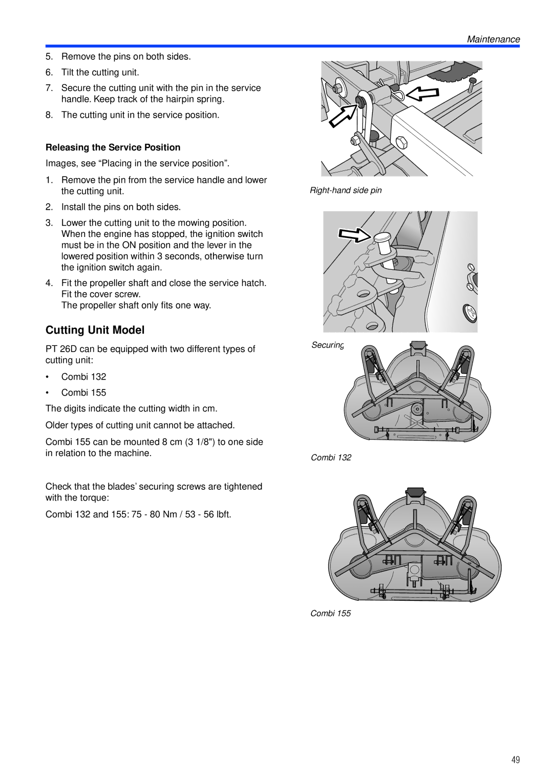
Cutting Unit Model
PT 26D can be equipped with two different types of cutting unit:
•Combi 132
•Combi 155
The digits indicate the cutting width in cm.
Older types of cutting unit cannot be attached.
Combi 155 can be mounted 8 cm (3 1/8") to one side in relation to the machine.
Check that the blades’ securing screws are tightened with the torque:
Combi 132 and 155: 75 - 80 Nm / 53 - 56 lbft.
Securing in the service position
Combi 132
Combi 155
49