Maintenance
IMPORTANT INFORMATION:
Do not touch the bulb glass with your fingers. Finger prints evaporate and mark the reflector.
5.Fold the wire loop for headlight lamp to one side and replace the bulb.
6.Assemble in the reverse order.
Light setting
Place the machine at least 5 m from a wall. The machine must stand flat.
The steering wheel console must be in the rear position.
Switch on the headlights.
The low beam's upper limit line must fall 1 cm for each metre distance to the wall, measure from the centre of the headlight.
Adjust with the screws (36) if necessary. These are accessible once the rear plastic cover around the steering wheel console has been removed.
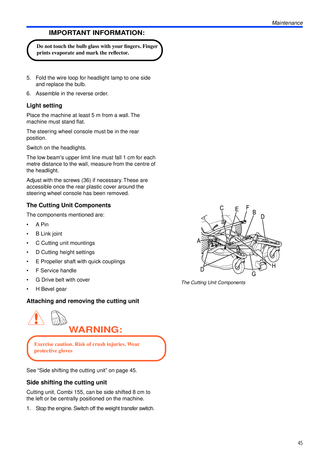
The Cutting Unit Components
The components mentioned are:
• | A Pin |
|
• | B Link joint |
|
• C Cutting unit mountings |
| |
• D Cutting height settings |
| |
• E Propeller shaft with quick couplings |
| |
• | F Service handle |
|
• G Drive belt with cover | The Cutting Unit Components | |
|
| |
•H Bevel gear
Attaching and removing the cutting unit
WARNING:
Exercise caution. Risk of crush injuries. Wear protective gloves
See “Side shifting the cutting unit” on page 45.
Side shifting the cutting unit
Cutting unit, Combi 155, can be side shifted 8 cm to the left or be centrally positioned on the machine.
1. Stop the engine. Switch off the weight transfer switch.
45