Maintenance
IMPORTANT INFORMATION:
Never leave the propeller shaft on the machine with one end detached. If the engine starts, damage might occur.
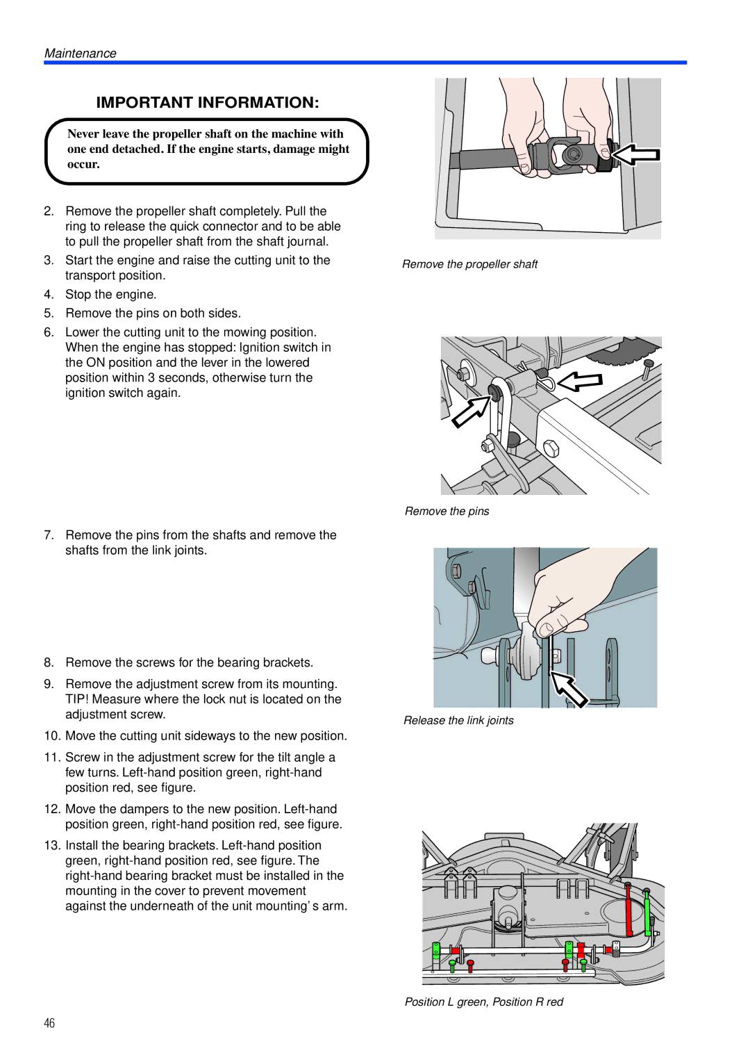
2.Remove the propeller shaft completely. Pull the ring to release the quick connector and to be able to pull the propeller shaft from the shaft journal.
3.Start the engine and raise the cutting unit to the transport position.
4.Stop the engine.
5.Remove the pins on both sides.
6.Lower the cutting unit to the mowing position. When the engine has stopped: Ignition switch in the ON position and the lever in the lowered position within 3 seconds, otherwise turn the ignition switch again.
7.Remove the pins from the shafts and remove the shafts from the link joints.
8.Remove the screws for the bearing brackets.
9.Remove the adjustment screw from its mounting. TIP! Measure where the lock nut is located on the adjustment screw.
10.Move the cutting unit sideways to the new position.
11.Screw in the adjustment screw for the tilt angle a few turns.
12.Move the dampers to the new position.
13.Install the bearing brackets.
Remove the propeller shaft
Remove the pins
Release the link joints
Position L green, Position R red
46