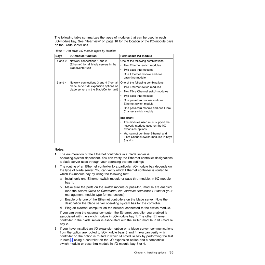
The following table summarizes the types of modules that can be used in each
Table 1.
Bays |
| Permissible I/O module |
1 and 2 Network connections 1 and 2 | One of the following combinations: | |
| (Ethernet) for all blade servers in the | v Two Ethernet switch modules |
| BladeCenter unit | v Two |
|
| |
|
| v One Ethernet module and one |
|
| |
|
| |
3 and 4 Network connections 3 and 4 (from all | One of the following combinations: | |
| blade server I/O expansion options on | v Two Ethernet switch modules |
| blade servers in the BladeCenter unit) | v Two Fibre Channel switch modules |
|
| v Two |
|
| v One |
|
| Ethernet switch module |
|
| v One |
|
| Channel switch module |
Important:
v The modules used must support the
network interface used on the I/O expansion options.
v You cannot combine Ethernet and Fibre Channel switch modules in bays 3 and 4.
Notes:
1.The enumeration of the Ethernet controllers in a blade server is
ablade server uses through your operating system settings.
2.The routing of an Ethernet controller to a particular
a.Install only one Ethernet switch module or
b.Make sure the ports on the switch module or
c.Enable only one of the Ethernet controllers on the blade server. Note the designation the blade server operating system has for the controller.
d.Ping an external computer on the network connected to the switch module.
If you can ping the external computer, the Ethernet controller you enabled is associated with the switch module in
3.If you have installed an I/O expansion option on a blade server, communications from the option are routed to
Chapter 4. Installing options 35