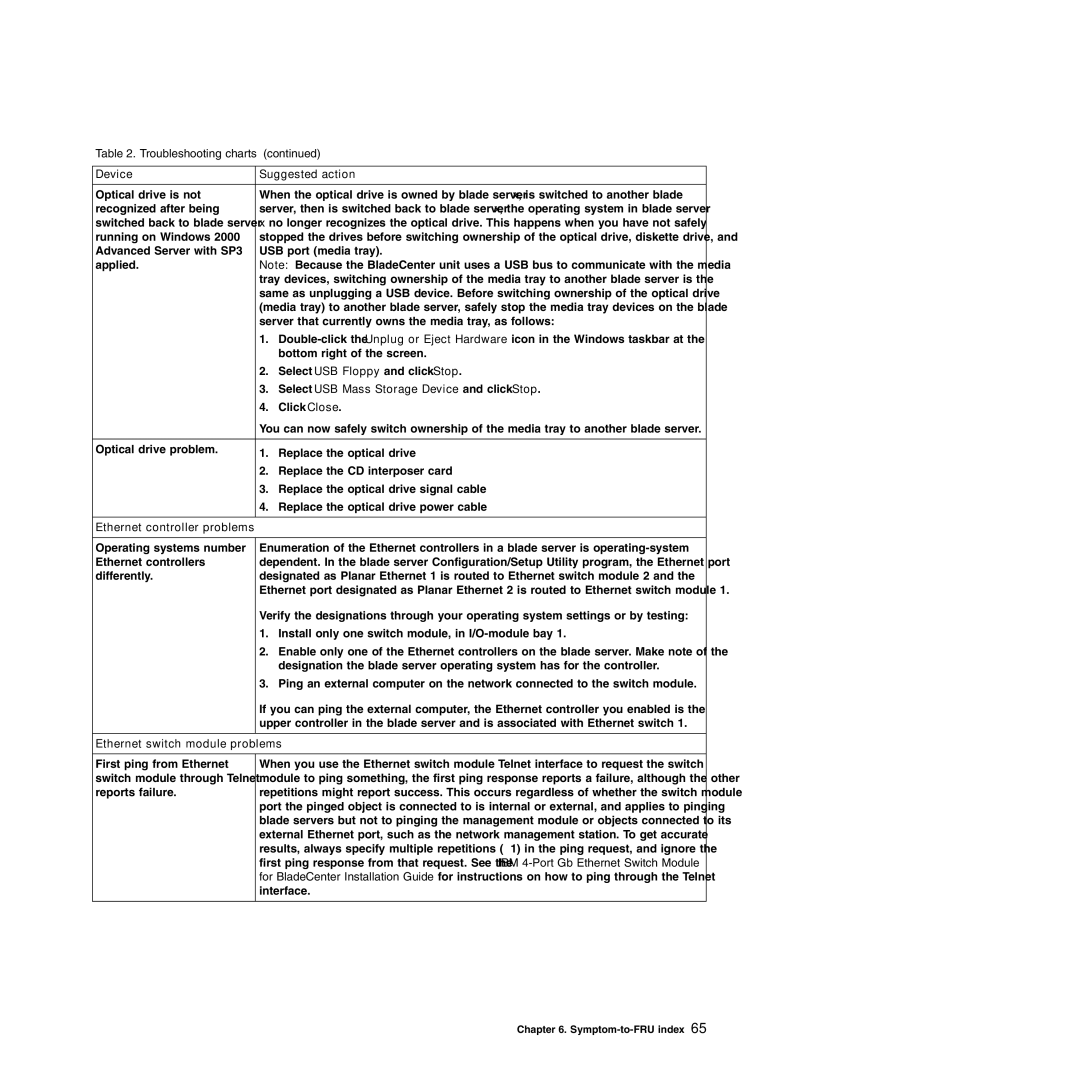
Table 2. Troubleshooting charts (continued)
Device | Suggested action | |
|
| |
Optical drive is not | When the optical drive is owned by blade server x, is switched to another blade | |
recognized after being | server, then is switched back to blade server x, the operating system in blade server | |
switched back to blade server | x no longer recognizes the optical drive. This happens when you have not safely | |
running on Windows 2000 | stopped the drives before switching ownership of the optical drive, diskette drive, and | |
Advanced Server with SP3 | USB port (media tray). | |
applied. | Note: Because the BladeCenter unit uses a USB bus to communicate with the media | |
| tray devices, switching ownership of the media tray to another blade server is the | |
| same as unplugging a USB device. Before switching ownership of the optical drive | |
| (media tray) to another blade server, safely stop the media tray devices on the blade | |
| server that currently owns the media tray, as follows: | |
| 1. | |
|
| bottom right of the screen. |
| 2. | Select USB Floppy and click Stop. |
| 3. | Select USB Mass Storage Device and click Stop. |
| 4. | Click Close. |
| You can now safely switch ownership of the media tray to another blade server. | |
|
|
|
Optical drive problem. | 1. | Replace the optical drive |
| ||
| 2. | Replace the CD interposer card |
| 3. | Replace the optical drive signal cable |
| 4. | Replace the optical drive power cable |
|
|
|
Ethernet controller problems |
|
|
|
| |
Operating systems number | Enumeration of the Ethernet controllers in a blade server is | |
Ethernet controllers | dependent. In the blade server Configuration/Setup Utility program, the Ethernet port | |
differently. | designated as Planar Ethernet 1 is routed to Ethernet switch module 2 and the | |
| Ethernet port designated as Planar Ethernet 2 is routed to Ethernet switch module 1. | |
| Verify the designations through your operating system settings or by testing: | |
| 1. | Install only one switch module, in |
| 2. | Enable only one of the Ethernet controllers on the blade server. Make note of the |
|
| designation the blade server operating system has for the controller. |
| 3. | Ping an external computer on the network connected to the switch module. |
| If you can ping the external computer, the Ethernet controller you enabled is the | |
| upper controller in the blade server and is associated with Ethernet switch 1. | |
|
| |
Ethernet switch module problems | ||
|
| |
First ping from Ethernet | When you use the Ethernet switch module Telnet interface to request the switch | |
switch module through Telnet | module to ping something, the first ping response reports a failure, although the other | |
reports failure. | repetitions might report success. This occurs regardless of whether the switch module | |
| port the pinged object is connected to is internal or external, and applies to pinging | |
| blade servers but not to pinging the management module or objects connected to its | |
| external Ethernet port, such as the network management station. To get accurate | |
| results, always specify multiple repetitions (>1) in the ping request, and ignore the | |
| first ping response from that request. See the IBM | |
| for BladeCenter Installation Guide for instructions on how to ping through the Telnet | |
| interface. | |
|
|
|
Chapter 6.
