Technical Information
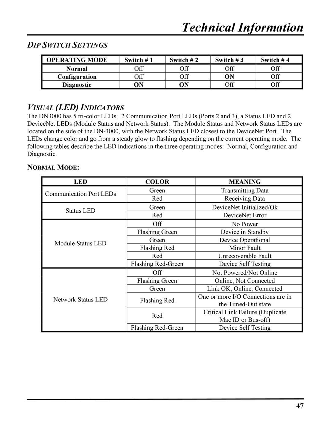
DIP SWITCH SETTINGS
OPERATING MODE | Switch # 1 | Switch # 2 | Switch # 3 | Switch # 4 |
Normal | Off | Off | Off | Off |
Configuration | Off | Off | ON | Off |
Diagnostic | ON | ON | Off | Off |
VISUAL (LED) INDICATORS
The DN3000 has 5
NORMAL MODE:
LED | COLOR | MEANING | |
Communication Port LEDs | Green | Transmitting Data | |
Red | Receiving Data | ||
| |||
Status LED | Green | DeviceNet Initialized/Ok | |
Red | DeviceNet Error | ||
| |||
| Off | No Power | |
| Flashing Green | Device in Standby | |
Module Status LED | Green | Device Operational | |
Flashing Red | Minor Fault | ||
| |||
| Red | Unrecoverable Fault | |
| Flashing | Device Self Testing | |
| Off | Not Powered/Not Online | |
| Flashing Green | Online, Not Connected | |
| Green | Link OK, Online, Connected | |
Network Status LED | Flashing Red | One or more I/O Connections are in | |
the | |||
|
| ||
| Red | Critical Link Failure (Duplicate | |
| Mac ID or | ||
|
| ||
| Flashing | Device Self Testing |
47