110
110
110
110V
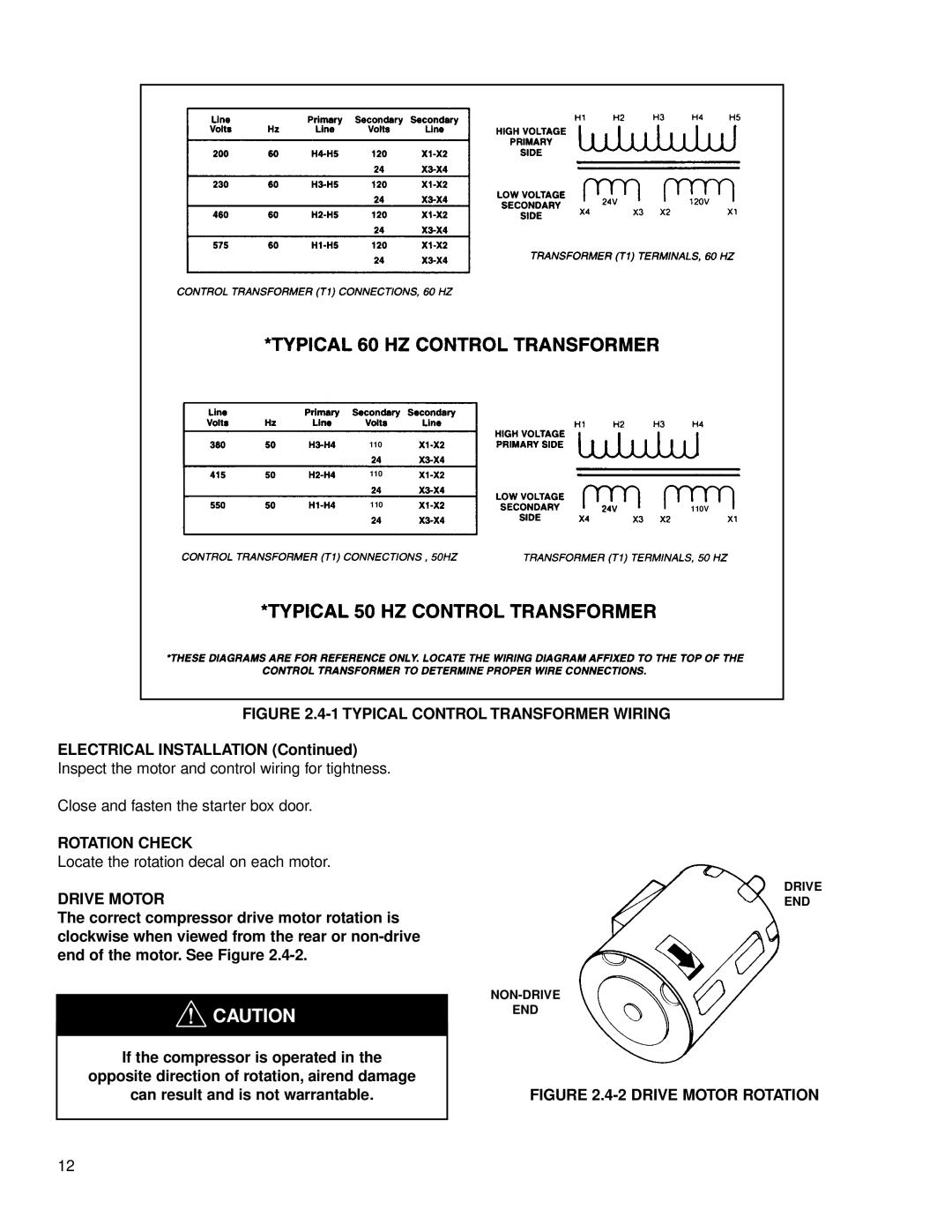
FIGURE 2.4-1 TYPICAL CONTROL TRANSFORMER WIRING
ELECTRICAL INSTALLATION (Continued) Inspect the motor and control wiring for tightness.
Close and fasten the starter box door.
ROTATION CHECK
Locate the rotation decal on each motor.
DRIVE MOTOR
The correct compressor drive motor rotation is clockwise when viewed from the rear or
![]() CAUTION
CAUTION
If the compressor is operated in the
opposite direction of rotation, airend damage
can result and is not warrantable.
DRIVE
END
END
FIGURE 2.4-2 DRIVE MOTOR ROTATION
12
