ELECTRICAL INSTALLATION (Continued)
The Intellisys will automatically shut the unit down if the compressor rotation is incorrect, and the display will indicate “CHECK MOTOR ROTATION” and will flash “ALARM”.
For the compressor motor rotation check, the motor jogging time must be as short as possible.
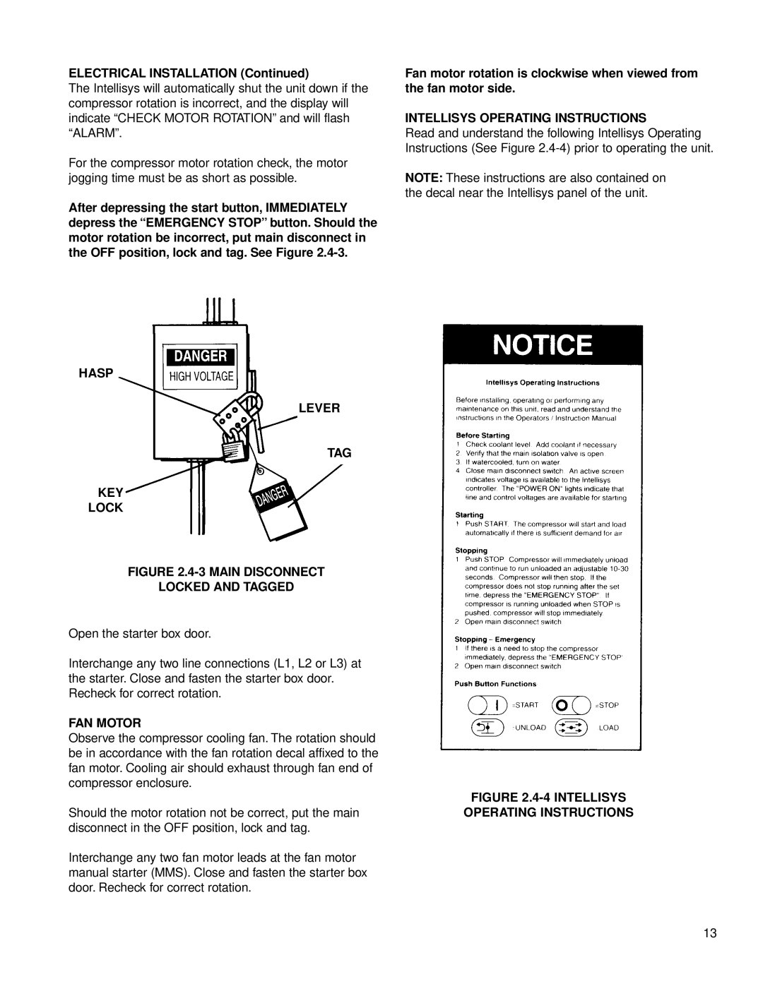
After depressing the start button, IMMEDIATELY depress the “EMERGENCY STOP” button. Should the motor rotation be incorrect, put main disconnect in the OFF position, lock and tag. See Figure
HASP
LEVER
TAG
KEY
LOCK
FIGURE 2.4-3 MAIN DISCONNECT
LOCKED AND TAGGED
Open the starter box door.
Interchange any two line connections (L1, L2 or L3) at the starter. Close and fasten the starter box door. Recheck for correct rotation.
FAN MOTOR
Observe the compressor cooling fan. The rotation should be in accordance with the fan rotation decal affixed to the fan motor. Cooling air should exhaust through fan end of compressor enclosure.
Should the motor rotation not be correct, put the main disconnect in the OFF position, lock and tag.
Interchange any two fan motor leads at the fan motor manual starter (MMS). Close and fasten the starter box door. Recheck for correct rotation.
Fan motor rotation is clockwise when viewed from the fan motor side.
INTELLISYS OPERATING INSTRUCTIONS
Read and understand the following Intellisys Operating Instructions (See Figure
NOTE: These instructions are also contained on the decal near the Intellisys panel of the unit.
FIGURE 2.4-4 INTELLISYS
OPERATING INSTRUCTIONS
13