6.0 TROUBLESHOOTING CHART
TROUBLE | CAUSE &/OR DISPLAY | WHAT TO DO | |
|
|
| |
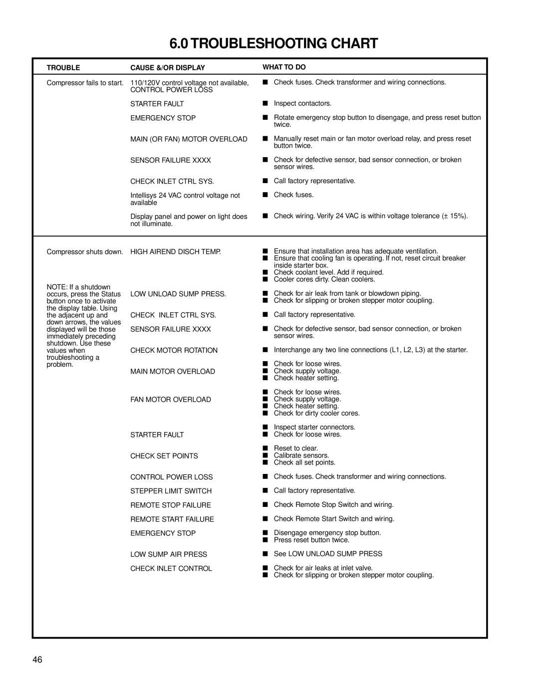
Compressor fails to start. | 110/120V control voltage not available, | ■ Check fuses. Check transformer and wiring connections. | |
| CONTROL POWER LOSS |
|
|
| STARTER FAULT | ■ | Inspect contactors. |
| EMERGENCY STOP | ■ Rotate emergency stop button to disengage, and press reset button | |
|
|
| twice. |
| MAIN (OR FAN) MOTOR OVERLOAD | ■ Manually reset main or fan motor overload relay, and press reset | |
|
|
| button twice. |
| SENSOR FAILURE XXXX | ■ Check for defective sensor, bad sensor connection, or broken | |
|
|
| sensor wires. |
| CHECK INLET CTRL SYS. | ■ | Call factory representative. |
| Intellisys 24 VAC control voltage not | ■ | Check fuses. |
| available |
|
|
| Display panel and power on light does | ■ | Check wiring. Verify 24 VAC is within voltage tolerance (± 15%). |
| not illuminate. |
|
|
Compressor shuts down. | HIGH AIREND DISCH TEMP. |
NOTE: If a shutdown |
|
occurs, press the Status | LOW UNLOAD SUMP PRESS. |
button once to activate |
|
the display table. Using |
|
the adjacent up and | CHECK INLET CTRL SYS. |
down arrows, the values |
|
displayed will be those | SENSOR FAILURE XXXX |
immediately preceding |
|
shutdown. Use these |
|
values when | CHECK MOTOR ROTATION |
troubleshooting a problem.
MAIN MOTOR OVERLOAD
FAN MOTOR OVERLOAD
STARTER FAULT
CHECK SET POINTS
CONTROL POWER LOSS
STEPPER LIMIT SWITCH
REMOTE STOP FAILURE
REMOTE START FAILURE
EMERGENCY STOP
LOW SUMP AIR PRESS
CHECK INLET CONTROL
■Ensure that installation area has adequate ventilation.
■Ensure that cooling fan is operating. If not, reset circuit breaker inside starter box.
■Check coolant level. Add if required.
■Cooler cores dirty. Clean coolers.
■Check for air leak from tank or blowdown piping.
■Check for slipping or broken stepper motor coupling.
■Call factory representative.
■Check for defective sensor, bad sensor connection, or broken sensor wires.
■Interchange any two line connections (L1, L2, L3) at the starter.
■Check for loose wires.
■Check supply voltage.
■Check heater setting.
■Check for loose wires.
■Check supply voltage.
■Check heater setting.
■Check for dirty cooler cores.
■Inspect starter connectors.
■Check for loose wires.
■Reset to clear.
■Calibrate sensors.
■Check all set points.
■Check fuses. Check transformer and wiring connections.
■Call factory representative.
■Check Remote Stop Switch and wiring.
■Check Remote Start Switch and wiring.
■Disengage emergency stop button.
■Press reset button twice.
■See LOW UNLOAD SUMP PRESS
■Check for air leaks at inlet valve.
■Check for slipping or broken stepper motor coupling.
46