3.4 MAIN MENU
|
|
|
|
|
|
|
|
|
|
|
|
|
| |||
|
|
|
|
|
|
|
|
|
|
|
| |||||
|
|
|
|
|
|
|
|
|
|
| Operator Setpoints | |||||
|
|
| 1 0 0 |
|
|
|
|
|
| |||||||
|
|
|
|
|
|
|
|
|
| Options | ||||||
|
|
|
| P S I | ||||||||||||
|
|
|
|
|
|
|
|
|
|
| Sensor Calibration | |||||
|
|
|
|
|
|
|
|
|
| |||||||
|
|
| Ready To Start |
|
| Alarm History | ||||||||||
|
|
|
|
|
|
|
|
|
|
| Clock Functions | |||||
|
|
|
|
|
|
|
|
|
|
| ||||||
|
|
|
|
|
|
|
|
|
|
|
|
|
|
|
|
|
|
|
| STATUS |
|
|
|
|
|
|
|
|
| SELECT |
|
|
|
|
|
|
|
|
|
|
|
|
|
|
|
|
|
|
|
|
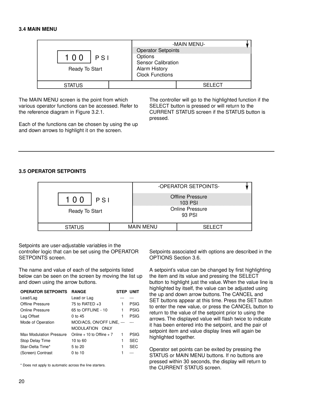
The MAIN MENU screen is the point from which various operator functions can be accessed. Refer to the reference diagram in Figure 3.2.1.
Each of the functions can be chosen by using the up and down arrows to highlight it on the screen.
The controller will go to the highlighted function if the SELECT button is pressed or will return to the CURRENT STATUS screen if the STATUS button is pressed.
3.5 OPERATOR SETPOINTS
1 0 0 P S I
Ready To Start
Offline Pressure
103PSI
Online Pressure 93 PSI
STATUS
MAIN MENU
SELECT
Setpoints are
The name and value of each of the setpoints listed below can be seen on the screen by moving the list up and down using the arrow buttons.
OPERATOR SETPOINTS | RANGE | STEP | UNIT |
Lead/Lag | Lead or Lag | ||
Offline Pressure | 75 to RATED +3 | 1 | PSIG |
Online Pressure | 65 to OFFLINE - 10 | 1 | PSIG |
Lag Offset | 0 to 45 | 1 | PSIG |
Mode of Operation | MOD/ACS, ON/OFF LINE, | ||
| MODULATION ONLY |
|
|
Max Modulation Pressure | Online + 10 to Offline + 7 | 1 | PSIG |
Stop Delay Time | 10 to 60 | 1 | SEC |
5 to 20 | 1 | SEC | |
(Screen) Contrast | 0 to 10 | 1 | |
* Does not apply to automatic across the line starters.
Setpoints associated with options are described in the OPTIONS Section 3.6.
A setpoint’s value can be changed by first highlighting the item and its value and pressing the SELECT button to highlight just the value. When the value line is highlighted by itself, the value can be adjusted using the up and down arrow buttons. The CANCEL and SET buttons appear at this time. Press the SET button to enter the new value, or press the CANCEL button to return to the value of the setpoint prior to using the arrows. The displayed value will flash twice to indicate it has been entered into the setpoint, and the pair of setpoint item and value display lines will again be highlighted together.
Operator set points can be exited by pressing the STATUS or MAIN MENU buttons. If no buttons are pressed within 30 seconds, the display will return to the CURRENT STATUS screen.
20
