“Status”
“Status” ![]()
“Main Menu” ![]()
CURRENT STATUS
“Main Menu”
MAIN MENU*
“Select”
Operator |
“Main Menu” | OPERATOR |
|
“Main Menu”![]()
OPTIONS**
“Main Menu”
SENSOR
“Main Menu”
ALARM
“Main Menu” |
CLOCK |
“Main Menu”
INTEGRAL
SETPOINTS** |
“Status” |
“Status”![]()
“Status”![]()
CALIBRATION**
“Status”![]()
HISTORY**
FUNCTIONS |
“Status” |
“Status”![]()
SEQUENCING
“Select” |
OPERATOR SETPOINTS ITEM***
“Select”
OPTIONS
ITEM***
“Select”
SENSOR
CALIBRATION
ITEM****
“Select”
“Main Menu” |
| ALARM |
| |
|
| |||
|
| HISTORY |
| |
“Status” |
| ITEM***** |
| |
|
| |||
|
|
|
|
|
|
|
|
|
|
|
|
|
|
|
|
|
|
|
|
|
|
|
|
|
|
|
|
| “Select” |
|
|
| |
“Main Menu” |
|
|
|
|
|
|
|
|
|
| |
| DATE AND |
|
| ||
|
|
| |||
|
|
|
| ||
“Status” |
| TIME |
|
| |
|
|
|
|
| |
|
|
|
|
| |
|
|
|
|
|
|
|
|
|
|
|
|
“Select”
“Main Menu” | INTEGRAL |
| SEQUENCING |
“Status” | ITEM*** |
Panel Flow Figure 3.2.1 | INTELLISYS |
Diagram |
|
“Cancel” or “Set” | “Cancel” or “Set” | “Cancel” or “Calibrate” | “Alarm Hist.” | “Cancel ot Set | “ | ot Set |
| “Cancel” or “set” | |||||
|
|
|
| or “set” |
|
|
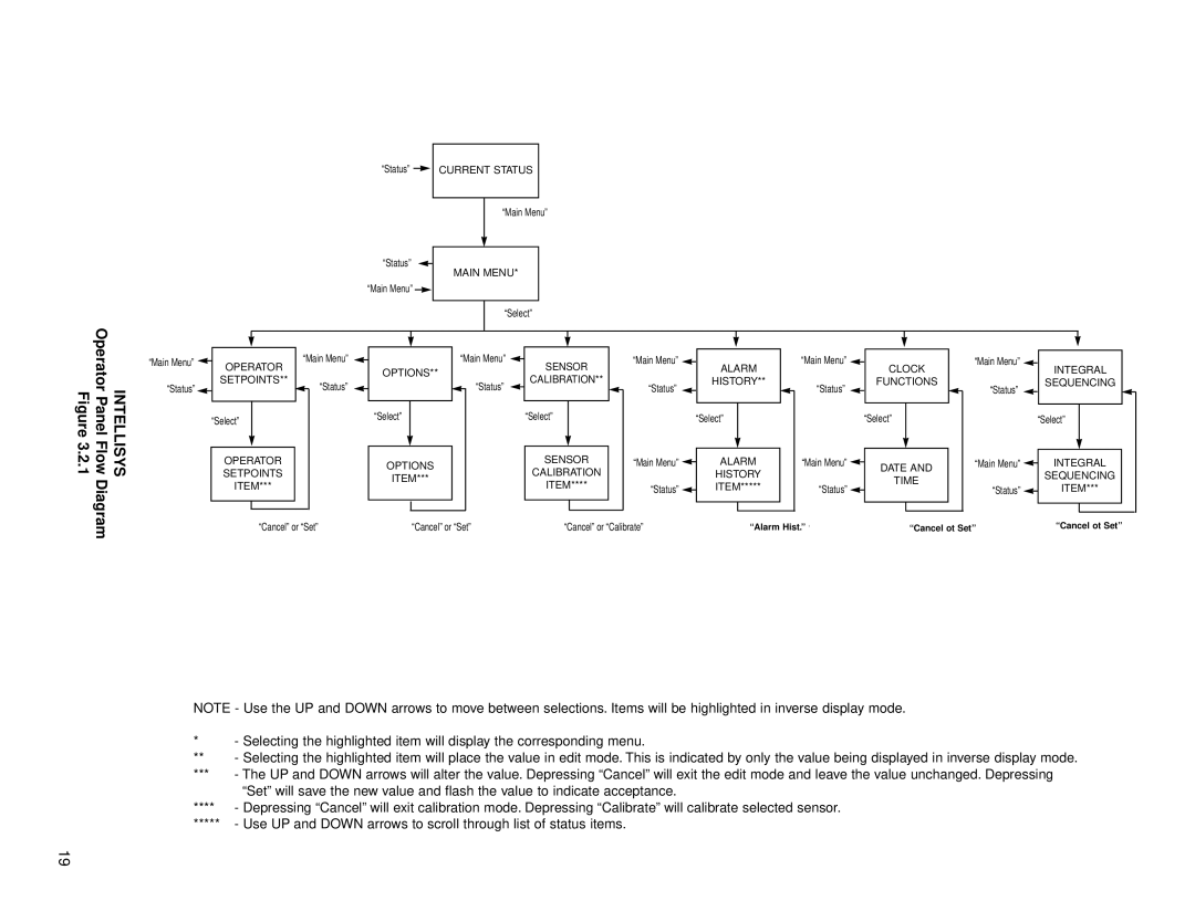
NOTE - Use the UP and DOWN arrows to move between selections. Items will be highlighted in inverse display mode.
*- Selecting the highlighted item will display the corresponding menu.
**- Selecting the highlighted item will place the value in edit mode. This is indicated by only the value being displayed in inverse display mode.
***- The UP and DOWN arrows will alter the value. Depressing “Cancel” will exit the edit mode and leave the value unchanged. Depressing “Set” will save the new value and flash the value to indicate acceptance.
****- Depressing “Cancel” will exit calibration mode. Depressing “Calibrate” will calibrate selected sensor.
*****- Use UP and DOWN arrows to scroll through list of status items.
19
