8051 Architectural Specification and Functional Description

REG~~TER 141... ---I/'-16---t1REGIST:~~~DIRECT I

'SPIs post-dec:remented.

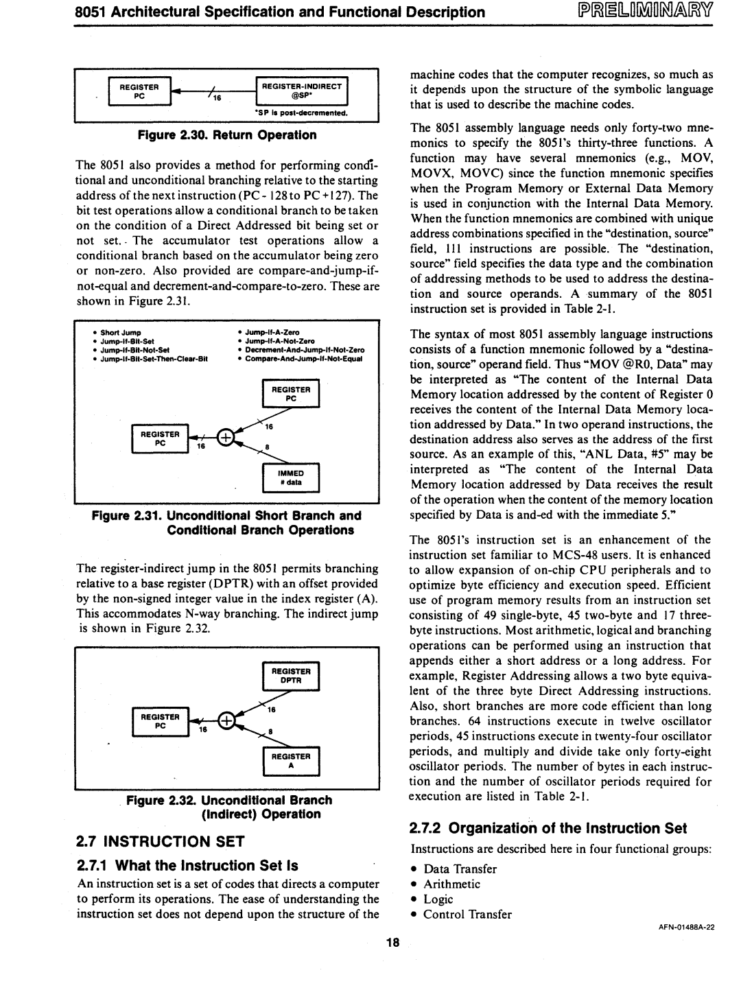
Figure 2.30. Return Operation

The 805 I also provides a method for performing condi- tional and unconditional branching relative to the starting address of the next instruction (PC - 128 to PC + 127). The bit test operations allow a conditional branch to be taken on the condition of a Direct Addressed bit being set or not set.· The accumulator test operations allow a conditional branch based on the accumulator being zero or non-zero. Also provided are compare-and-jump-if- not-equal and decrement-and-compare-to-zero. These are shown in Figure 2.31.

Short Jump

Jump-If-A-Zero

Jump-If-Blt-Sel

Jump-If-A-Not-Zero

Jump-If-Blt-Not-Set

Dec:remenl-And-Jump-If-Nol-Zero

Jump-If-Bil-Set-Then-Clear-Sit

Compare-And-Jump-ll-Not-Equal

Figure 2.31. Unconditional Short Branch and

Conditional Branch Operations

The register-indirect jump in the 8051 permits branching relative to a base register (DPTR) with an offset provided by the non-signed integer value in the index register (A). This accommodates N-way branching. The indirect jump is shown in Figure 2.32.

. Figure 2.32. Unconditional Branch (Indirect) Operation

machine codes that the computer recognizes, so much as it depends upon the structure of the symbolic language that is used to describe the machine codes.

The 8051 assembly language needs only forty-two mne- monics to specify the 8051 's thirty-three functions. A function may have several mnemonics (e.g., MOV, MOVX, MOVq since the function mnemonic specifies when the Program Memory or External Data Memory is used in conjunction with the Internal Data Memory. When the function mnemonics are combined with unique address combinations specified in the "destination, source" field, III instructions are possible. The "destination, source" field specifies the data type and the combination of addressing methods to be used to address the destina- tion and source operands. A summary of the 8051 instruction set is provided in Table 2-1.

The syntax of most 805 I assembly language instructions consists of a function mnemonic followed by a "destina- tion, source" operand field. Thus "MOV @RO, Data" may be interpreted as "The content of the Internal Data Memory location addressed by the content of Register 0 receives the content of the Internal Data Memory loca- tion addressed by Data." In two operand instructions, the destination address also serves as the address of the first source. As an example of this, "ANL Data, #5" may be interpreted as "The content of the Internal Data Memory location addressed by Data receives the result of the operation when the content of the memory location specified by Data is and-ed with the immediate 5."

The 8051 's instruction set is an enhancement of the instruction set familiar to MCS-48 users. It is enhanced to allow expansion of on-chip CPU peripherals and to optimize byte efficiency and execution speed. Efficient use of program memory results from an instruction set consisting of 49 single-byte, 45 two-byte and 17 three- byte instructions. Most arithmetic, logical and branching operations can be performed using an instruction that appends either a short address or a long address. For example, Register Addressing allows a two byte equiva- lent of the three byte Direct Addressing instructions. Also, short branches are more code efficient than long branches. 64 instructions execute in twelve oscillator periods, 45 instructions execute in twenty-four oscillator periods, and mUltiply and divide take only forty-eight oscillator periods. The number of bytes in each instruc- tion and the number of oscillator periods required for execution are listed in Table 2-1.

2.7INSTRUCTION SeT

2.7.1What the Instruction Set Is

An instruction set is a set of codes that directs a computer to perform its operations. The ease of understanding the instruction set does not depend upon the structure of the

2.7.2Organization of the Instruction Set

Instructions are described here in four functional groups:

Data Transfer

Arithmetic

Logic

Control Transfer

AFN-01488A-22

18

Page 23
Image 23
Intel 8051 manual Instruction SeT What the Instruction Set Is, Organization of the Instruction Set