8051 Architectural Specification and Functional Description
COUNTERI
GATETIMER
TIMERIRUN COUNTER
OIN MODE 3
~
G
Hn PULSE TO
SERIAL
PORT
COUNTER 1
MODE 0:
MODE 1:
MODE 2:
MODE 3: PREVENTS INCREMENTING OF TIC 1
INTERRUPT
REQUEST
J- )
INT1
T1
-- ~ J >-r-r-
1"'"
~r~ - r - :=fJ- -
| XTAL1 | +12 | 1- | ~ |
| COUNTER 0 |
| - | "' |
|
| ||
|
|
|
| ~ | ||
|
|
|
|
| ~ | (THO) |
|
|
| Figure 2.5.8. Timer/Counter 1 Control and Status Flag Circuitry | |||
• 100r11 Bit Frame | r - - - | |||||
• | Baud Rate Generetlon I |
|
|
| INTERRUPT | |
| from Oscillator or | I |
|
|
| I |
| Timer 1 |
|
|
| ||
• | Address Frame | I |
|
|
|
|
| Recognition |
|
|
| ||
|
| I |
| SCON |
|
|
|
| I |
| (SERIAL CONTROL) |
|
|
|
|
|
|
|
| |
|
| I |
| CONTROL" |
|
|
|
| I |
| TIMING CIRCUITRY |
|
|
|
|
|
|
|
| |
|
|
|
|
| ||
|
|
|
|
|
| |
| TIMER 1 | L ______________~~ ___ _ | ||||
| OVERFLOW |
|
|
|
| RECEIVER |
|
|
|
|
|
| RECEIVE |
|
|
|
|
|
| DATA |
|
|
|
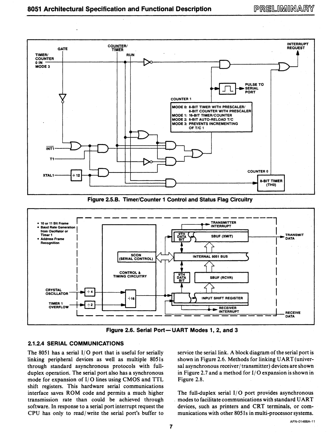
| Figure 2.6. Serial Port~UART Modes 1, 2, and 3 | ||
2.1.2.4 SERIAL COMMUNICATIONS |
|
| ||||
The 8051 has a serial I/O port that is useful for serially |
| service the serial link. A block diagram of the serial port is | ||||
linking peripheral devices as well as multiple805ls |
| shown in Figure 2.6. Methods for linking UART (univer- | ||||
through standard asynchronous protocols with full- |
| sal asynchronous receiver / transmitter) devices are shown | ||||
duplex operatiori. The serial port also has a synchronous |
| in Figure 2.7 and a method for I/O expansion is shown in | ||||
mode for expansion of I/O lines using CMOS and TTL |
| Figure 2.8. | ||||
shift registers. This hardware serial communications |
|
| ||||
interface saves ROM code and permits a much higher |
| The | ||||
transmission rate | than could | be achieved through | o | modes to facilitate communications with standard UART | ||
software. In response to a serial port interrupt request the |
| devices, such as printers and CRT terminals, or com- | ||||
CPU has only to read/write the serial port's buffer to |
| munications with other 8051s in | ||||
7