8051 Architectural Specification and Functional Description
The SJMP (short jump) instruction provides for transfers within a 256 byte range centered about the starting address of the next instruction
JMP@ A+DPTR performs ajump relative to the DPTR register. The operand in the A register is used as the offset
Conditional Jumps. In the control transfer group, the con- ditional jumps perform a jump contingent upon a specific condition. The destination will be within a
JZ performs a jump if the accumulator is zero. JNZ performs a jump if the accumulator is not zero.
JC performs a jump if the carry flag is set.
JNC performs a jump if the carry flag is not set. JB performs a jump if the Direct Addressed bit is set.
JNB performs a jump if the Direct Addressed bit is not set.
JBC performs a jump if the Direct Addressed bit is set and then clears the Direct Addressed bit. CJNE compares the first operand to the second operand and performs a jump if they are not equal. C is set if the first operand is less than the second operand; else it is cleared. Comparis"ons can be made between the A register and Direct Address- able bytes in the Internal Data Memory or between an immediate value and either the A register, an RB register in the selected Register Bank, or a
DJNZ decrements the source operand and returns the result to the operand. A jump is performed if the result is not zero. The DJNZ instruction makes a RAM location efficient for use as a program loop counter by allowing the programmer to decrement and test the counter in a single instruction. The source operand of the DJNZ instruction may be any byte in the Internal Data Memory. Either Direct or Register Addressing may be used to address the source operand.
Interrupts. Program execution control may be transferred by means of internal and external interrupts. All interrupts perform a transfer by pushing the Program Counter onto the stack and then branching to programs located at absolute locations 3, II, 19, 27, and 35 in the Program Memory. The programmer must push all registers that will be altered by his interrupt service program onto the
stack to avoid corruption. Only one interrupt transfer operation is necessary:
RETI transfers control in a manner identical to ' RET. In addition, RET! reenables interrupts for the current priority level.
See section 2.8 for further details on the operation and control of the interrupt system.
2.7.3 Operand Addressing Modes & Associated Operations
In section 2.4 the instruction set was explained from the point of view of which operands could be used with each operation. This section lists the operations that can be used with each addressing method.
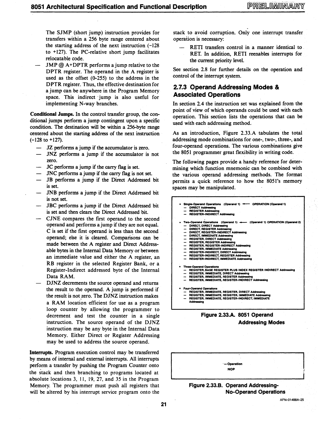
As an introduction, Figure 2.33.A tabulates the total addressing mode combinations for
The following pages provide a handy reference for deter- mining which function mnemonic can be combined with the various operand addressing methods. The format permits a quick reference to how the 8051's memory spaces may be manipulated.
• | SIngte.O_d O_allon. (O _ d 1) - | OPERATION (Operud 1) | |
| - | DIRECTA_g |
|
| - | REGISTER AddntooIng |
|
| - |
| |
• | Tw.... | O _...d Operallon. (Operand 1) _ | (Operand 11 OPERATION (Ope<and 2) |
-DIRECT, DIRECT A _ lng DIRECT, REGISTER Addreoolng DIRECT.
DIRECT, IMMEDIATE A _ V REGISTER, DIRECT A _ g REGISTER, REGISTER Add _ g REGISTER,
•Th......Ope<and Opendlona
-REGISTER, BASE REGISTER PLUS INDEX REGISTER INDIRECT Addr..slng
-REGISTER, IMMEDIATE, DIRECT Addreoolng
-REGISTER, IMMEDIATE, REGISTER Ad_lng
-REGISTER. IMMEDIATE,
•
-REGISTER, IMMEDIATE, REGISTER, DIRECT Addreoolng
-REGISTER, IMMEDIATE, REGISTER. IMMEDIATE Ad _ ng
-REGISTER, IMMEDIATE,
Figure 2.33.A. 8051 Operand
Addressing Modes
NOP
Figure 2.33.B. Operand Addressing-
No-Operand Operations
21
