8051 Architectural Specification and Functional Description
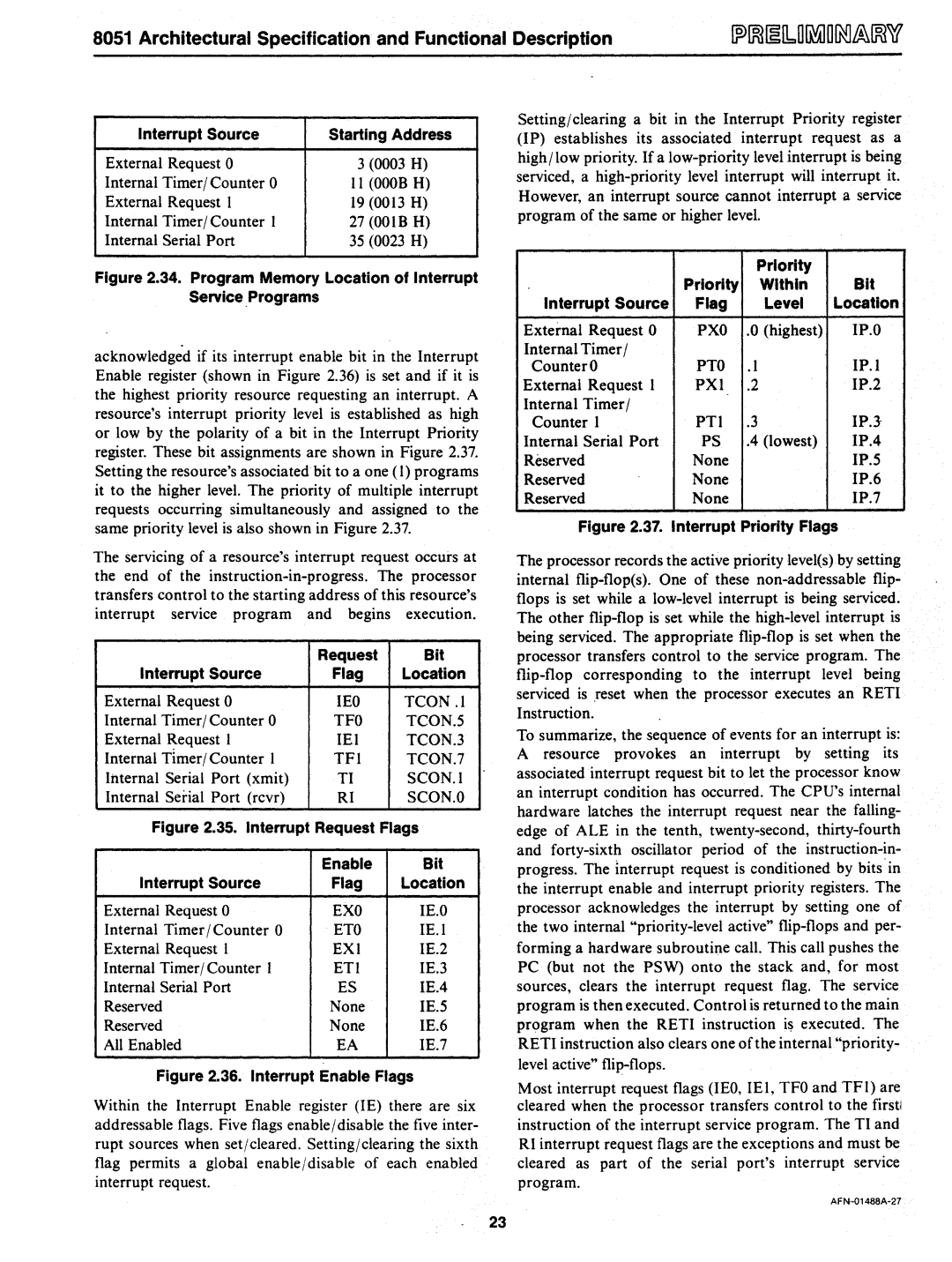
Interrupt Source | Starting Address | |
External Request 0 | 3 (0003 H) | |
Internal Timer/Counter 0 | II (OOOB H) | |
External Request I | 19 | (0013 H) |
Internal Timer/ Counter I | 27 | (OOIB H) |
Internal Serial Port | 35 (0023 H) | |
Figure 2.34. Program Memory Location of Interrupt Service Programs
Setting/ clearing a bit in the Interrupt Priority register (IP) establishes its associated interrupt request as a high/low priority. If a
Priority
Priority Within Bit
Interrupt Source Flag Level Location
acknowledged if its interrupt enable bit in the Interrupt Enable register (shown in Figure 2.36) is set and if it is the highest priority resource requesting an interrupt. A resource's interrupt priority level is established as high or low by the polarity of a bit in the Interrupt Priority register. These bit assignments are shown in Figure 2.37. Setting the resource's associated bit to a one (1) programs it to the higher level. The priority of mUltiple interrupt requests occurring simultaneously and assigned to the same priority level is also shown in Figure 2.37.
The servicing of a resource's interrupt request occurs at the end of the
| Request | Bit |
Interrupt Source | Flag | Location |
External Request 0 | lEO | TCON .1 |
Internal Timer/ Counter 0 | TFO | TCON.5 |
External Request I | lEI | TCON.3 |
Internal Timer/ Counter I | TFI | TCON.7 |
Internal Serial Port (xmit) | TI | SCON.I |
Internal Serial Port (rcvr) | RI | SCON.O |
Figure 2.35. Interrupt Request Flags | ||
| Enable | Bit |
Interrupt Source | Flag | Location |
External Request 0 | EXO | lE.O |
Internal Timer / Counter 0 | ETO | IE.! |
External Request I | EXI | 1E.2 |
Internal Timer/ Counter 1 | ETI | IE.3 |
Internal Serial Port | ES | 1E.4 |
Reserved | None | 1E.5 |
Reserved | None | 1E.6 |
All Enabled | EA | 1E.7 |
Figure 2.36. Interrupt Enable Flags
Within the Interrupt Enable register (IE) there are six addressable flags. Five flags enable /disable the five inter- rupt sources when set/cleared. Setting/clearing the sixth flag permits a global enable Idisable of each enabled interrupt request.
External Request 0 | PXO | .0 | (highest) | IP.O |
Internal Timer / | PTO |
|
| IP.l |
Counter 0 | .1 |
| ||
External Request 1 | PXl | .2 |
| IP.2 |
Internal Timer/ | PTI | .3 |
| IP.J |
Counter I |
| |||
Internal Serial Port | PS | .4 | (lowest) | IP.4 |
Reserved | None |
|
| IP.5 |
Reserved | None |
|
| IP.6 |
Reserved | None |
|
| IP.7 |
Figure 2.37. Interrupt Priority Flags
The processor records the active priority level(s) by setting internal
To summarize, the sequence of events for an interrupt is: A resource provokes an interrupt by setting its associated interrupt request bit to let the processor know an interrupt condition has occurred. The CPU's internal hardware latches the interrupt request near the falling- edge of ALE in the tenth,
Most interrupt request flags (lEO, lEt, TFO and TFl) are cleared when the processor transfers control to the firstl instruction of the interrupt service program. The TI and RI interrupt request flags are the exceptions and must be cleared as part of the serial port's interrupt service program.
23