8051 Architectural Specification and Functional Description
I.~~
I
TXD RXD | TXD RXD | TXD RXD | RXD TXD | TXD RXD | TXD RXD | TXD |
|
|
|
|
|
|
|
|
|
|
|
| RXD | ~. | TXD |
|
|
|
|
|
|
| ||
|
|
|
|
|
| PORT PIN |
| CTS |
8051 | 8051 | 8051 | 8051 | 8051 | 8051 | 8051 |
| 8251 |
A. | B. | C. | ||||||
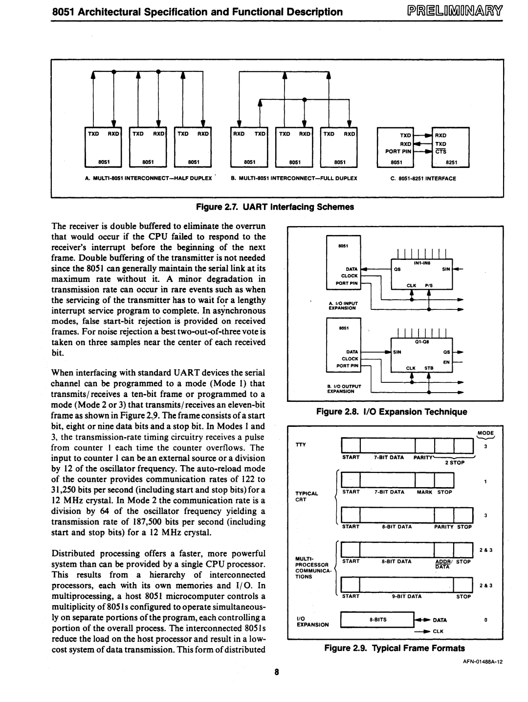
Figure 2.7. UART Interfacing Schemes
The receiver is double buffered to eliminate the overrun that would occur if the CPU failed to respond to the receiver's interrupt before the beginning of the next frame. Double buffering of the transmitter is not needed since the 8051 can generally maintain the serial link at its maximum rate without it. A minor degradation in transmission rate can occur in rare events such as when the servicing of the transmitter has to wait for a lengthy interrupt service program to complete. In asynchronous modes, false
When interfacing with standard UART devices the serial channel can be programmed to a mode (Mode 1) that transmits/ receives a
Distributed processing offers a faster, more powerful system than can be provided by a single CPU processor. This results from a hierarchy of interconnected processors, each with its own memories and 1/ O. In multiprocessing, a host 8051 microcomputer controls a multiplicity of 8051 s configured to operate simultaneous- lyon separate portions of the program, each controlling a portion of the overall process. The interconnected 8051 s reduce the load on the host processor and result in a low- cost system of data transmission. This form of distributed
8051
DATA
CLOCK
PORT PIN
A.1I0INPUT
EXPANSION
8051
DATAOS
CLOCK
EN
PORT PIN
B.110 OUTPUT EXPANSION
Figure 2.8. I/O Expansion Technique
|
|
|
|
| MODE |
TTY |
| ||||
| START | PARITY' | , | ||
|
| ||||
|
|
|
| 2 STOP |
|
TYPICAL | START | 7·BITDATA | MARK | STOP |
|
|
|
|
|
| |
CRT |
|
|
|
|
|
| START |
| PARITY STOP |
| |
|
|
|
|
| 2&3 |
MULTI- | START |
| ~~~:I STOP |
| |
PROCESSOR |
|
| |||
|
|
|
| ||
COMMUNICA- |
|
|
|
|
|
TIONS |
|
|
|
|
|
|
|
|
|
| 2&3 |
| START | STOP |
| ||
1/0 |
| a·BITS | j..DATA | o | |
EXPANSION | ClK |
| |||
|
| ||||
Figure 2.9. Typical Frame Formats
8