8051 Architectural Specification and Functional Description
The functions of the bits in TMOD are shown in Figure
2.45.Recall from section 2.3 that the bits in TMOD are not bit addressable.
Function |
| Bit |
Flag | Location | |
Enable input at TI using INTI | Gate | TMOD.7 |
Counter 1/ Timer 1 select | CIT | TMOD.6 |
C I/T 1 Mode select MSb | Ml | TMOD.5 |
C I/T I Mode select LSb | MO | TMOD.4 |
Enable input to TO using INTO | Gate | TMOD.3 |
Counter 0/ Timer 0 select | - | TMOD.2 |
CIT | ||
C OfT 0 Mode select MSb | Ml | TMOD.l |
C 0/ T 0 Mode select LSb | MO | TMOD.O |
Figure 2.45. Functions of Bits in TMOD
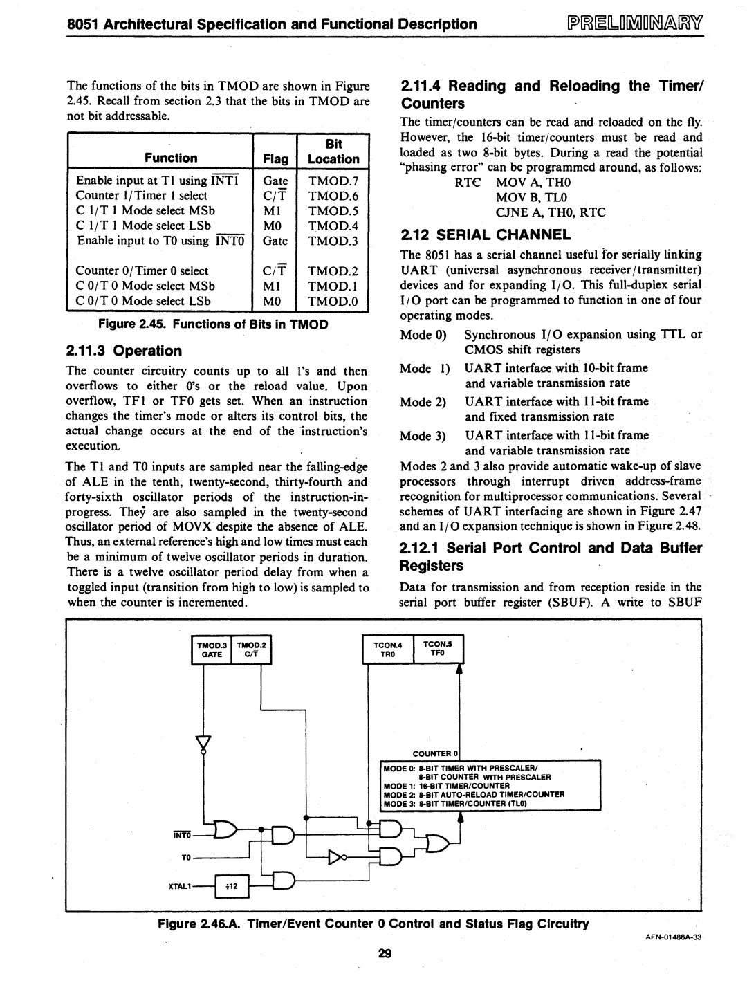
2.11.3 Operation
The counter circuitry counts up to all l's and then overflows to either O's or the reload value. Upon overflow, TFI or TFO gets set. When an instruction changes the timer's mode or alters its control bits, the actual change occurs at the end of the instruction's execution.
The T I and TO inputs are sampled near the
2.11.4Reading and Reloading the Timer/ Counters
The timer/counters can be read and reloaded on the fly. However, the
RTC MOV A, THO MOVB, TLO CJNE A, THO, RTC
2.12 SERIAL CHANNEL
The 8051 has a serialchannel useful for serially linking UART (universal asynchronous receiver/transmitter) devices and for expanding I/O. This
Mode 0) Synchronous I/O expansion using TIL or CMOS shift registers
Mode 1) UART interface with
Mode 2) UART interface with
Mode 3) UART interface with
Modes 2 and 3 also provide automatic
2.12.1Serial Port Control and Data Buffer Registers
Data for transmission and from reception reside in the serial port buffer register (SBUF). A write to SBUF
COUNTER 0
MODE 0:
MODE 1:
MODE 2:
MODE 3:
TO
XTAL1
Figure 2.46.A. Timer/Event Counter 0 Control and Status Flag Circuitry
29