6 Technical Reference
Server Board Jumpers
5 |
|
|
| A |
|
| J5A2 |
|
6 | 2 |
|
| 3 | E |
|
| |
| 1 | J4B2 |
| J1D4 |
|
B CMOSCLR/ |
| |
C PSWDCLR/ |
| |
D RCVR/BOOT |
| |
|
| OM14142 |
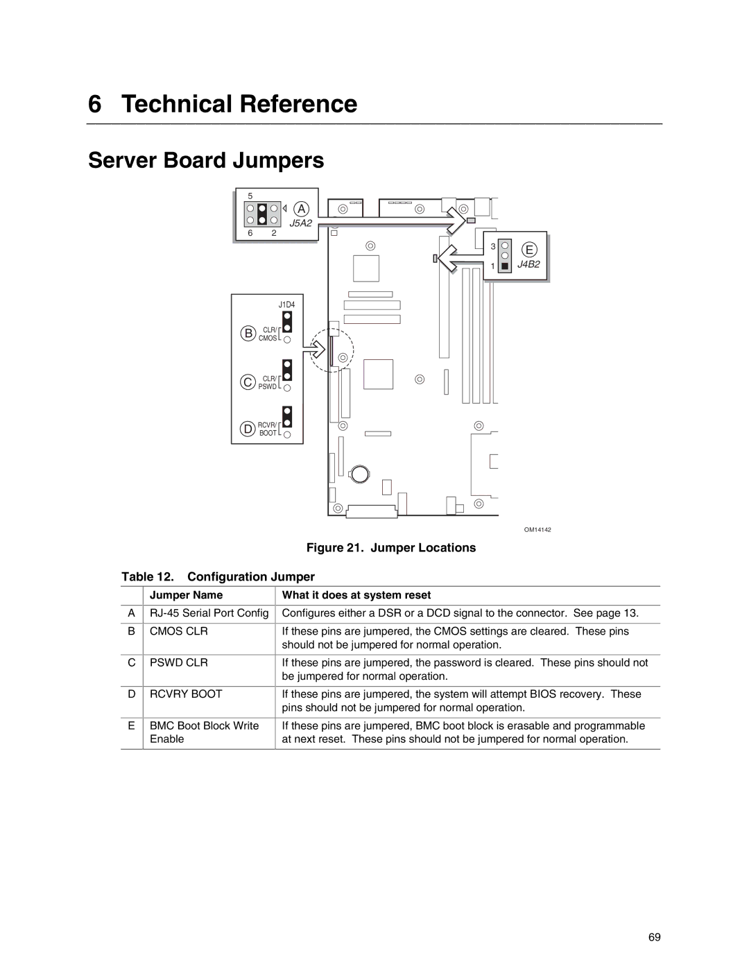
Figure 21. Jumper Locations
Table 12. Configuration Jumper
A
B
C
Jumper Name
CMOS CLR
PSWD CLR
What it does at system reset
Configures either a DSR or a DCD signal to the connector. See page 13.
If these pins are jumpered, the CMOS settings are cleared. These pins should not be jumpered for normal operation.
If these pins are jumpered, the password is cleared. These pins should not be jumpered for normal operation.
D
RCVRY BOOT
If these pins are jumpered, the system will attempt BIOS recovery. These pins should not be jumpered for normal operation.
E
BMC Boot Block Write Enable
If these pins are jumpered, BMC boot block is erasable and programmable at next reset. These pins should not be jumpered for normal operation.
69
