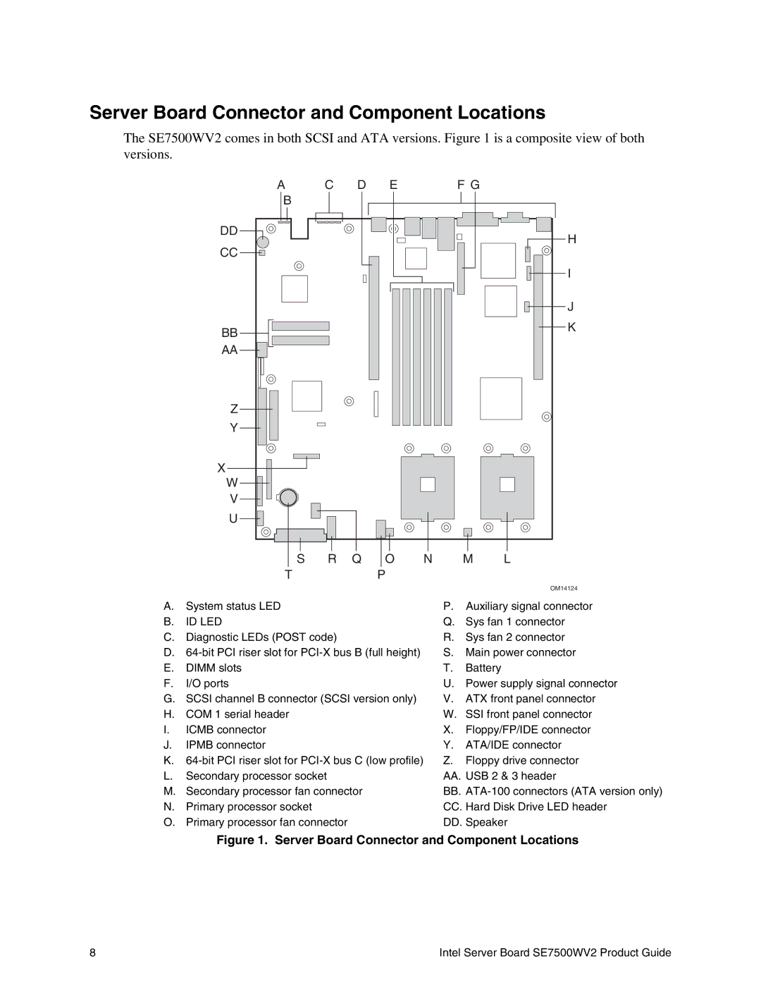
Server Board Connector and Component Locations
The SE7500WV2 comes in both SCSI and ATA versions. Figure 1 is a composite view of both versions.
A C D E F G
B
DD | H | |
CC | ||
| ||
| I | |
| J | |
BB | K | |
| ||
AA |
|
|
| Z |
|
|
|
|
|
|
|
|
|
|
|
|
|
|
|
|
|
|
|
|
|
|
|
|
|
|
|
|
|
|
|
|
|
|
|
|
|
|
|
|
|
|
|
|
|
|
|
|
|
|
|
|
|
|
|
|
|
|
|
|
|
|
|
|
|
|
|
|
|
|
|
|
|
|
|
|
|
|
|
|
|
|
|
|
|
|
|
|
|
|
|
|
|
| |
|
|
|
|
|
|
|
|
|
|
|
|
|
|
|
|
|
|
|
|
|
|
|
|
|
|
|
|
|
|
|
|
|
|
|
|
|
|
|
|
|
|
|
|
| ||||
|
|
|
|
|
|
|
|
|
|
|
|
|
|
|
|
|
|
|
|
|
|
|
|
|
|
|
|
|
|
|
|
|
|
|
|
|
|
|
|
|
|
|
|
| ||||
|
|
|
|
|
|
|
|
|
|
|
|
|
|
|
|
|
|
|
|
|
|
|
|
|
|
|
|
|
|
|
|
|
|
|
|
|
|
|
|
|
|
|
|
|
|
|
| |
| X | Y |
|
|
|
|
|
|
|
|
|
|
|
|
|
|
|
|
|
|
|
|
|
|
|
|
|
|
|
|
|
|
|
|
|
|
|
|
|
|
|
|
|
|
| |||
|
|
|
|
|
|
|
|
|
|
|
|
|
|
|
|
|
|
|
|
|
|
|
|
|
|
|
|
|
|
|
|
|
|
|
|
|
|
|
|
|
|
| ||||||
|
|
|
|
|
|
|
|
|
|
|
|
|
|
|
|
|
|
|
|
|
|
|
|
|
|
|
|
|
|
|
|
|
|
|
|
|
|
|
|
|
|
|
| |||||
|
|
|
|
|
|
|
|
|
|
|
|
|
|
|
|
|
|
|
|
|
|
|
|
|
|
|
|
|
|
|
|
|
|
|
|
|
|
|
|
|
|
|
|
|
| |||
|
|
|
|
|
|
|
|
|
|
|
|
|
|
|
|
|
|
|
|
|
|
|
|
|
|
|
|
|
|
|
|
|
|
|
|
|
|
|
|
|
|
|
|
|
|
|
| |
|
|
|
|
|
|
|
|
|
|
|
|
|
|
|
|
|
|
|
|
|
|
|
|
|
|
|
|
|
|
|
|
|
|
|
|
|
|
|
|
|
|
|
|
|
| |||
|
|
|
|
|
|
|
|
|
|
|
|
|
|
|
|
|
|
|
|
|
|
|
|
|
|
|
|
|
|
|
|
|
|
|
|
|
|
|
|
|
|
|
| |||||
|
|
|
|
|
|
|
|
|
|
|
|
|
|
|
|
|
|
|
|
|
|
|
|
|
|
|
|
|
|
|
|
|
|
|
|
|
|
|
|
|
|
|
| |||||
| W |
|
|
|
|
|
|
|
|
|
|
|
|
|
|
|
|
|
|
|
|
|
|
|
|
|
|
|
|
|
|
|
|
|
|
|
|
|
|
|
|
|
|
|
| |||
|
| V |
|
|
|
|
|
|
|
|
|
|
|
|
|
|
|
|
|
|
|
|
|
|
|
|
|
|
|
|
|
|
|
|
|
|
|
|
|
|
|
|
|
|
| |||
|
|
|
|
|
|
|
|
|
|
|
|
|
|
|
|
|
|
|
|
|
|
|
|
|
|
|
|
|
|
|
|
|
|
|
|
|
|
|
|
|
|
|
|
| ||||
|
|
|
|
|
|
|
|
|
|
|
|
|
|
|
|
|
|
|
|
|
|
|
|
|
|
|
|
|
|
|
|
|
|
|
|
|
|
|
|
|
|
|
|
| ||||
|
| U |
|
|
|
|
|
|
|
|
|
|
|
|
|
|
|
|
|
|
|
|
|
|
|
|
|
|
|
|
|
|
|
|
|
|
|
|
|
|
|
|
|
|
|
| ||
|
|
|
|
|
|
|
|
|
|
|
|
|
|
|
|
|
|
|
|
|
|
|
|
|
|
|
|
|
|
|
|
|
|
|
|
|
|
|
|
|
|
|
|
|
| |||
|
|
|
|
|
|
|
|
|
|
|
|
|
|
|
|
|
|
|
|
|
|
|
|
|
|
|
|
|
|
|
|
|
|
|
|
|
|
|
|
|
|
|
|
| ||||
|
|
|
|
|
|
|
|
|
|
|
|
|
|
|
|
|
|
|
|
|
|
|
|
|
|
|
|
|
|
|
|
|
|
|
|
|
|
|
|
|
|
|
|
|
|
|
|
|
|
|
|
|
|
|
|
|
|
|
|
|
|
|
|
|
|
|
|
|
|
|
|
|
|
|
|
|
|
|
|
|
| ||||||||||||||||
|
|
|
|
|
|
|
|
|
|
|
|
|
|
|
|
|
|
|
|
|
|
|
|
|
|
|
|
|
|
|
| |||||||||||||||||
|
|
|
|
|
|
|
|
|
|
| S | R Q | O | N |
|
|
|
|
| M | L | |||||||||||||||||||||||||||
|
|
|
|
|
|
|
|
| T |
|
|
| P |
|
|
|
|
|
|
|
|
|
|
|
|
|
|
|
|
|
|
|
| |||||||||||||||
|
|
|
|
|
|
|
|
|
|
|
|
|
|
|
|
|
|
|
|
|
|
|
|
|
|
|
|
|
|
|
|
|
|
|
|
|
|
|
|
|
|
|
|
|
|
| OM14124 | |
A. | System status LED |
|
|
|
|
|
|
|
|
|
|
|
|
|
|
|
|
| P. |
| Auxiliary signal connector | |||||||||||||||||||||||||||
B. | ID LED |
|
|
|
|
|
|
|
|
|
|
|
|
|
|
|
|
| Q. Sys fan 1 connector | |||||||||||||||||||||||||||||
C. | Diagnostic LEDs (POST code) |
|
|
|
|
|
|
|
|
|
|
|
|
|
| R. Sys fan 2 connector | ||||||||||||||||||||||||||||||||
D. |
|
|
|
|
| S. |
| Main power connector | ||||||||||||||||||||||||||||||||||||||||
E. | DIMM slots |
|
|
|
|
|
|
|
|
|
|
|
|
|
|
|
|
| T. |
| Battery |
|
|
|
|
|
|
| ||||||||||||||||||||
F. | I/O ports |
|
|
|
|
|
|
|
|
|
|
|
|
|
|
|
|
| U. Power supply signal connector | |||||||||||||||||||||||||||||
G. | SCSI channel B connector (SCSI version only) |
|
|
|
|
| V. ATX front panel connector | |||||||||||||||||||||||||||||||||||||||||
H. | COM 1 serial header |
|
|
|
|
|
|
|
|
|
|
|
|
|
|
|
|
| W. SSI front panel connector | |||||||||||||||||||||||||||||
I. | ICMB connector |
|
|
|
|
|
|
|
|
|
|
|
|
|
|
|
|
| X. |
| Floppy/FP/IDE connector | |||||||||||||||||||||||||||
J. | IPMB connector |
|
|
|
|
|
|
|
|
|
|
|
|
|
|
|
|
| Y. |
| ATA/IDE connector | |||||||||||||||||||||||||||
K. |
|
|
|
|
| Z. |
| Floppy drive connector | ||||||||||||||||||||||||||||||||||||||||
L. | Secondary processor socket |
|
|
|
|
|
|
|
|
|
|
|
|
|
|
|
|
| AA. USB 2 & 3 header | |||||||||||||||||||||||||||||
M. | Secondary processor fan connector |
|
|
|
|
|
|
|
|
|
|
|
|
|
| BB. | ||||||||||||||||||||||||||||||||
N. | Primary processor socket |
|
|
|
|
|
|
|
|
|
|
|
|
|
|
|
|
| CC. Hard Disk Drive LED header | |||||||||||||||||||||||||||||
O. | Primary processor fan connector |
|
|
|
|
|
|
|
|
|
|
|
|
|
| DD. Speaker | ||||||||||||||||||||||||||||||||
Figure 1. Server Board Connector and Component Locations
8 | Intel Server Board SE7500WV2 Product Guide |