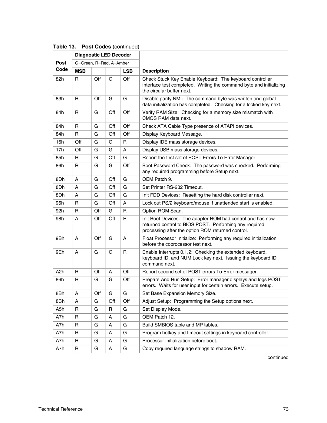
Table 13. Post Codes (continued)
Diagnostic LED Decoder
Post | G=Green, R=Red, A=Amber | |||
Code | MSB |
|
| LSB |
|
|
| ||
82h | R | Off | G | Off |
|
|
|
|
|
Description
Check Stuck Key Enable Keyboard: The keyboard controller interface test completed. Writing the command byte and initializing the circular buffer next.
83h
R
Off G
G
Disable parity NMI: The command byte was written and global data initialization has completed. Checking for a locked key next.
84h
84h
84h
16h
17h
85h
86h
8Dh
8Dh
8Dh
95h
92h
98h
9Bh
R
R
R
Off
Off
R
R
A
A
A
R
R
A
A
G | Off | Off |
|
|
|
G | Off | Off |
|
|
|
G | Off | Off |
|
|
|
G | G | R |
G | G | A |
|
|
|
G | Off | G |
|
|
|
G | G | Off |
|
|
|
G | Off | G |
|
|
|
G | Off | G |
|
|
|
G | Off | G |
|
|
|
G | Off | A |
|
|
|
Off | G | R |
Off | Off | R |
|
|
|
Off | G | A |
|
|
|
Verify RAM Size: Checking for a memory size mismatch with CMOS RAM data next.
Check ATA Cable Type presence of ATAPI devices.
Display Keyboard Message.
Display IDE mass storage devices.
Display USB mass storage devices.
Report the first set of POST Errors To Error Manager.
Boot Password Check: The password was checked. Performing any required programming before Setup next.
OEM Patch 9.
Set Printer
Init FDD Devices: Resetting the hard disk controller next.
Lock out PS/2 keyboard/mouse if unattended start is enabled.
Option ROM Scan.
Init Boot Devices: The adapter ROM had control and has now returned control to BIOS POST. Performing any required processing after the option ROM returned control.
Float Processor Initialize: Performing any required initialization before the coprocessor test next.
9Eh
A2h
86h
8Bh
8Ch
A5h
A7h
A7h
A7h
A7h
A7h
A
R
R
A
A
R
R
R
R
R
R
G | G | R |
|
|
|
Off | A | Off |
G | G | Off |
|
|
|
Off | G | G |
|
|
|
G | Off | Off |
|
|
|
G | R | G |
|
|
|
G | A | G |
|
|
|
G | A | G |
|
|
|
G | A | G |
|
|
|
G | A | G |
G | A | G |
|
|
|
Enable Interrupts 0,1,2: Checking the extended keyboard, keyboard ID, and NUM Lock key next. Issuing the keyboard ID command next.
Report second set of POST errors To Error messager.
Prepare And Run Setup: Error manager displays and logs POST errors. Waits for user input for certain errors. Execute setup.
Set Base Expansion Memory Size.
Adjust Setup: Programming the Setup options next.
Set Display Mode.
OEM Patch 12.
Build SMBIOS table and MP tables.
Program hotkey and timeout settings in keyboard controller.
Processor initialization before boot.
Copy required language strings to shadow RAM.
continued
Technical Reference | 73 |
