SECTION
2.Depending on the model of wheel lock installed on the wheelchair, perform one (1) of the following:
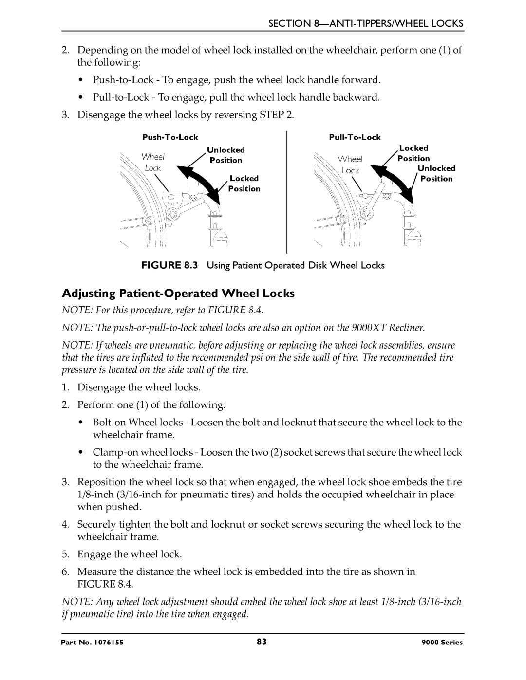
•Push‐to‐Lock ‐ To engage, push the wheel lock handle forward.
•Pull‐to‐Lock ‐ To engage, pull the wheel lock handle backward.
3.Disengage the wheel locks by reversing STEP 2.
| |
Wheel | Unlocked |
Position | |
Lock |
|
| Locked |
| Position |
Locked
Wheel Position
LockUnlocked
![]() Position
Position
FIGURE 8.3 Using Patient Operated Disk Wheel Locks
Adjusting Patient-Operated Wheel Locks
NOTE: For this procedure, refer to FIGURE 8.4.
NOTE: The push‐or‐pull‐to‐lock wheel locks are also an option on the 9000XT Recliner.
NOTE: If wheels are pneumatic, before adjusting or replacing the wheel lock assemblies, ensure that the tires are inflated to the recommended psi on the side wall of tire. The recommended tire pressure is located on the side wall of the tire.
1.Disengage the wheel locks.
2.Perform one (1) of the following:
•Bolt‐on Wheel locks ‐ Loosen the bolt and locknut that secure the wheel lock to the wheelchair frame.
•Clamp‐on wheel locks ‐ Loosen the two (2) socket screws that secure the wheel lock to the wheelchair frame.
3.Reposition the wheel lock so that when engaged, the wheel lock shoe embeds the tire 1/8‐inch (3/16‐inch for pneumatic tires) and holds the occupied wheelchair in place when pushed.
4.Securely tighten the bolt and locknut or socket screws securing the wheel lock to the wheelchair frame.
5.Engage the wheel lock.
6.Measure the distance the wheel lock is embedded into the tire as shown in FIGURE 8.4.
NOTE: Any wheel lock adjustment should embed the wheel lock shoe at least 1/8‐inch (3/16‐inch if pneumatic tire) into the tire when engaged.
Part No. 1076155 | 83 | 9000 Series |