SECTION 7—RECLINER
Removing/Installing Rear Wheels
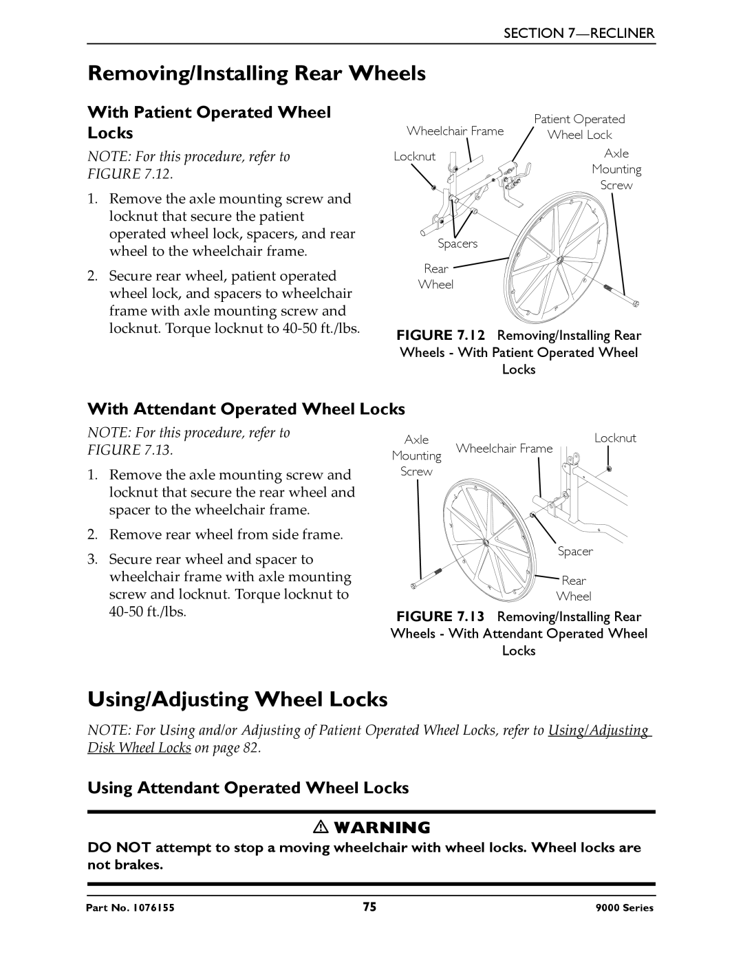
With Patient Operated Wheel Locks
NOTE: For this procedure, refer to FIGURE 7.12.
Wheelchair Frame | Patient Operated |
Wheel Lock | |
Locknut | Axle |
| Mounting |
| Screw |
1.Remove the axle mounting screw and locknut that secure the patient operated wheel lock, spacers, and rear wheel to the wheelchair frame.
2.Secure rear wheel, patient operated wheel lock, and spacers to wheelchair frame with axle mounting screw and locknut. Torque locknut to 40‐50 ft./lbs.
With Attendant Operated Wheel Locks
NOTE: For this procedure, refer to FIGURE 7.13.
1.Remove the axle mounting screw and locknut that secure the rear wheel and spacer to the wheelchair frame.
2.Remove rear wheel from side frame.
3.Secure rear wheel and spacer to wheelchair frame with axle mounting screw and locknut. Torque locknut to 40‐50 ft./lbs.
Axle | Wheelchair Frame | Locknut | |
Mounting |
|
| |
|
|
| |
Screw |
|
|
|
Spacer
![]()
![]() Rear
Rear
Wheel
FIGURE 7.13 Removing/Installing Rear
Wheels - With Attendant Operated Wheel
Locks
Using/Adjusting Wheel Locks
NOTE: For Using and/or Adjusting of Patient Operated Wheel Locks, refer to Using/Adjusting Disk Wheel Locks on page 82.
Using Attendant Operated Wheel Locks
WARNING
DO NOT attempt to stop a moving wheelchair with wheel locks. Wheel locks are not brakes.
Part No. 1076155 | 75 | 9000 Series |