SECTION 7—RECLINER
DETAIL “A” - WHEEL LOCK SHOE ENGAGEMENT
Wheel Lock | ||
Shoe | ||
pneumatic tires) |
| |
Wheel Lock |
| |
| Shoe |
|
Tire | Tire Contact | Tire |
| ||
| Area | Section |
Bolt and Locknut | Recliner Tube | |
Wheel Lock Handle |
| |
|
| |
Wheel Lock |
|
|
Shoe |
| Rear Wheel |
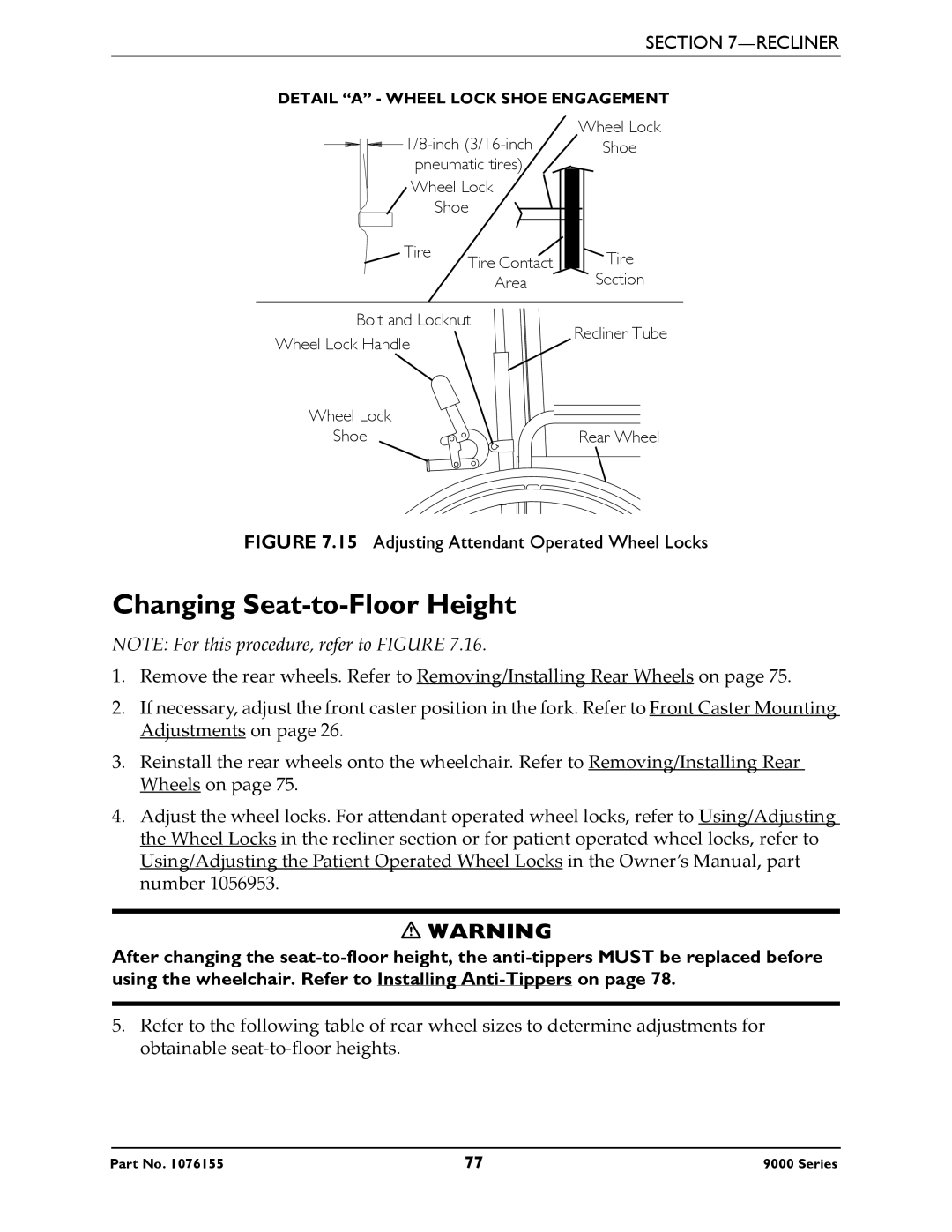
FIGURE 7.15 Adjusting Attendant Operated Wheel Locks
Changing Seat-to-Floor Height
NOTE: For this procedure, refer to FIGURE 7.16.
1.Remove the rear wheels. Refer to Removing/Installing Rear Wheels on page 75.
2.If necessary, adjust the front caster position in the fork. Refer to Front Caster Mounting Adjustments on page 26.
3.Reinstall the rear wheels onto the wheelchair. Refer to Removing/Installing Rear Wheels on page 75.
4.Adjust the wheel locks. For attendant operated wheel locks, refer to Using/Adjusting the Wheel Locks in the recliner section or for patient operated wheel locks, refer to Using/Adjusting the Patient Operated Wheel Locks in the Owner’s Manual, part number 1056953.
WARNING
After changing the
5.Refer to the following table of rear wheel sizes to determine adjustments for obtainable seat‐to‐floor heights.
Part No. 1076155 | 77 | 9000 Series |
