76![]()
![]()
![]()
![]()
![]()
CONTROLS,
 INDICATION
 S A
S A ND
ND CONNE
CONNE CTOR
CTOR S (Cont.)
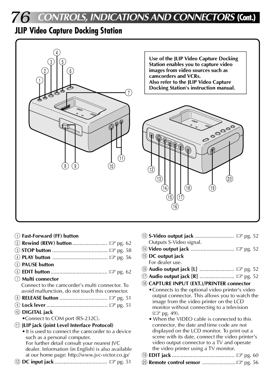
JLIP Video Capture Docking Station
4
35
2 6
1
7
!
8 9 | 0 |
Use of the JLIP Video Capture Docking Station enables you to capture video images from video sources such as camcorders and VCRs.
Also refer to the JLIP Video Capture Docking Station's instruction manual.
@![]()
#)
$ * (
%&
^
1
2 Rewind (REW) button | ☞ pg. 62 |
3 STOP button | ☞ pg. 58 |
4 PLAY button | ☞ pg. 56 |
5 PAUSE button |
|
6 EDIT button | ☞ pg. 62 |
7Multi connector
Connect to the camcorder’s multi connector. To avoid malfunction, do not touch this connector.
8 RELEASE button | ☞ pg. 51 |
9 Lock lever | ☞ pg. 51 |
0DIGITAL jack
•Connect to COM port
!JLIP jack (joint Level Interface Protocol)
•It is used to connect the camcorder to a device such as a personal computer.
For further detail consult your nearest JVC dealer. Information (in English) is also available at our home page:
@ DC input jack | ☞ pg. 51 |
# | ☞ pg. 52 |
Outputs |
|
$ Video output jack | ☞ pg. 52 |
% DC output jack |
|
For dealer use. |
|
^ Audio output jack [L] | ☞ pg. 52 |
& Audio output jack [R] | ☞ pg. 52 |
*CAPTURE INPUT (EXT.)/PRINTER connector •Connects to the optional video printer's video
output connector. This allows you to watch the image from the video printer on the LCD
monitor without connecting to a television (☞ pg. 49).
•When the VIDEO cable is connected to this connector, the date and time code are not displayed on the LCD monitor. To print out a scene with its date, connect the video printer's video output connector to a TV and operate the video printer using a TV monitor.
( EDIT jack | ☞ pg. 60 |
) Remote control sensor | ☞ pg. 56 |