12

 EN
EN 


 CONNECTIONS
■To assure safety, make sure all units are turned off before making any connections.
■The video images will be displayed on the LCD screen of the attached
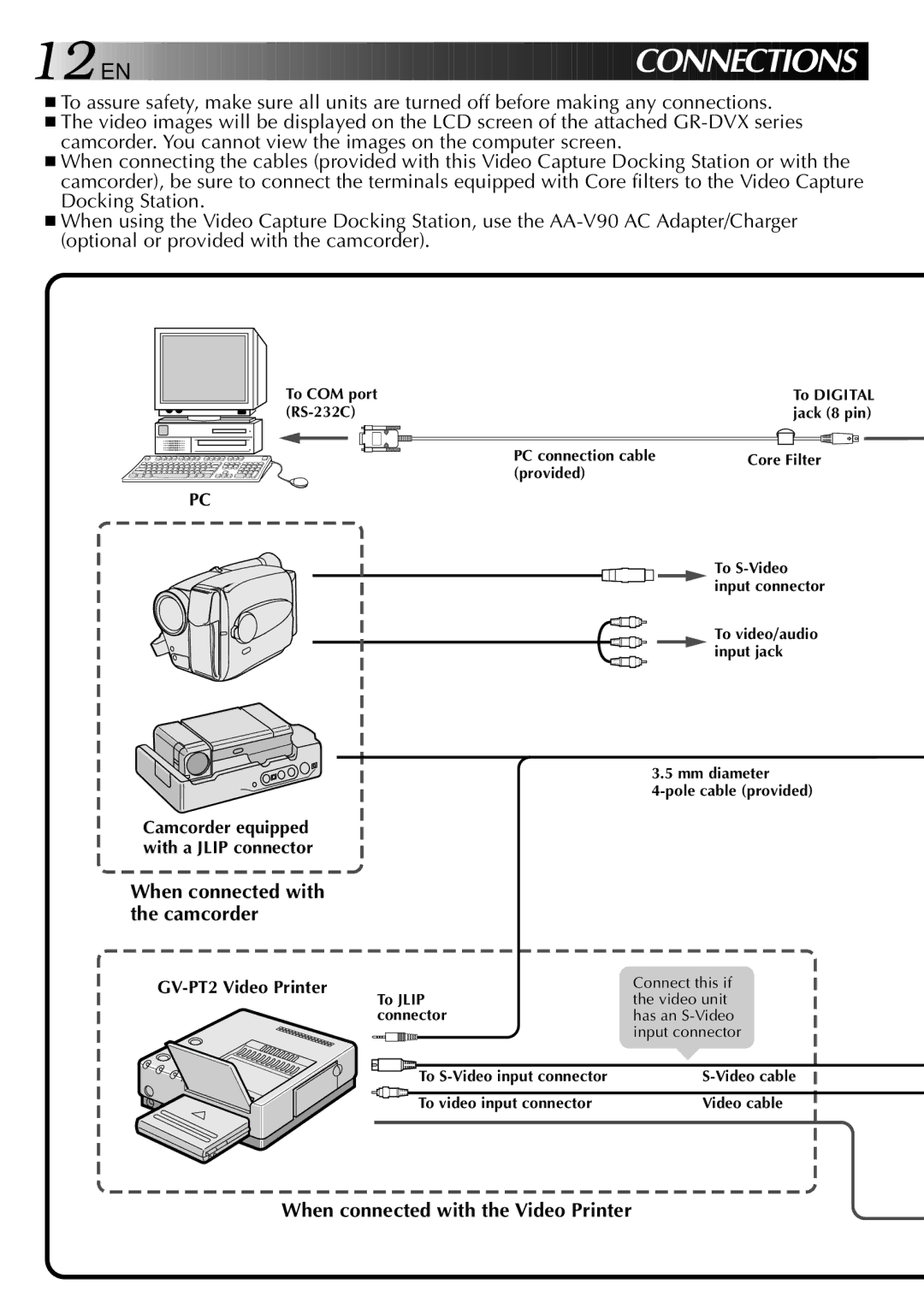
■When connecting the cables (provided with this Video Capture Docking Station or with the camcorder), be sure to connect the terminals equipped with Core filters to the Video Capture Docking Station.
■When using the Video Capture Docking Station, use the
To COM port
PC
Camcorder equipped with a JLIP connector
To DIGITAL jack (8 pin)
PC connection cable | Core Filter |
(provided) |
|
To
To video/audio input jack
3.5 mm diameter
When connected with the camcorder
GV-PT2 Video Printer
| Connect this if |
To JLIP | the video unit |
connector | has an |
| input connector |
To | |
To video input connector | Video cable |
