1. INTRODUCTION
2. CONTROLS, INDICATORS AND CONNECTORS
1-6 Condensation
●If the unit has been cooled down in a cold place and is then carried to a warm place, the moisture contained in the warm air may adhere to the head drum or tape guides and be cooled into water droplets. This phenomenon is referred to as condensation (dewing). When this occurs, the head drum and tape guides are covered with droplets allowing the tape to be stuck to them, leading to tape damage.
●“CONDENSATION ON DRUM” is displayed on the LCD monitor and in the viewfinder when condensation occurs in this unit.
WARNING 0201
2-1 Front Section
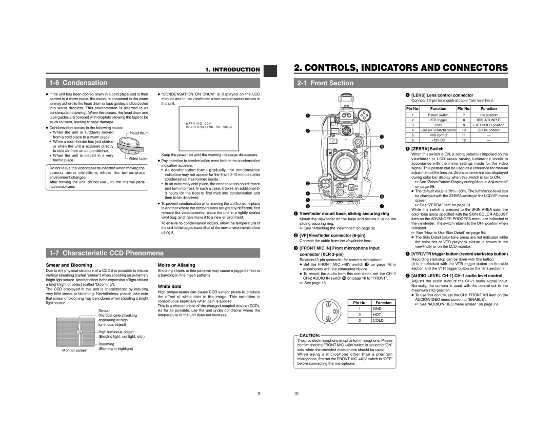
q
4[LENS] Lens control connector
Connect
Pin No. | Function | Pin No. | Function |
1 | Return switch | 7 | Iris position |
2 | VTR trigger | 8 | IRIS A/R INPUT |
|
|
|
|
3 | GND | 9 | EXTENDER position |
●Condensation occurs in the following cases:
•When the unit is suddenly moved from a cold place to a warm place.
•When a room heater has just started
or when the unit is exposed directly to cold air from an air conditioner.
•When the unit is placed in a very humid place.
![]() Head drum
Head drum
![]() Video tape
Video tape
CONDENSATION ON DRUM
Keep the power on until the warning message disappears.
● Pay attention to condensation even before the condensation |
indication appears. |
w
!0
VF
![]() o
o
4 | Lens AUTO/MANU control | 10 | ZOOM position |
5 | IRIS control | 11 | — |
6 | +12V DC | 12 | — |
5 [ZEBRA] Switch |
When this switch is ON, a zebra pattern is imposed on the |
viewfinder or LCD areas having luminance levels in |
accordance with the menu settings made for the video |
Do not leave the videocassette inserted when moving the camera under conditions where the temperature environment changes.
After moving the unit, do not use until the internal parts have stabilized.
• As condensation forms gradually, the condensation |
indication may not appear for the first |
condensation has formed inside. |
• In an extremely cold place, the condensation could freeze |
and turn into frost. In such a case, it takes an additional 2- |
3 hours for the frost to first melt into condensation and |
then to be dissolved. |
● To prevent condensation when moving the unit from one place |
to another where the temperatures are greatly defferent, first |
remove the videocassette, place the unit in a tightly sealed |
vinyl bag, and then move it to a new environment. |
To ensure no condensation occurs, allow the temperature of |
the unit in the bag to reach that of the new environment before |
using it. |
e | OFF | ZEBRA |
|
|
ON | SKIN | AUTO |
| |
| AREA | WHITE |
| |
|
|
| ACCU |
|
|
|
| FOCUS |
|
r |
| VTR | AUDIO |
|
|
| LEVELE | i | |
|
|
| 5 | |
t |
|
|
|
|
y |
|
|
| u |
1Viewfinder mount base, sliding securing ring
Mount the viewfinder on the base and secure it using the sliding securing ring.
☞ See “Attaching the Viewfinder” on page 32.
2[VF] Viewfinder connector (6-pin)
Connect the cable from the viewfinder here.
signal. This pattern can be used as a reference for manual |
adjustment of the lens iris. Zebra patterns are also displayed |
during color bar display when this switch is set to ON. |
☞ See “Zebra Pattern Display during Manual Adjustment” |
on page 89. |
● The default value is 70% - 80%. The luminance level can |
be changed with the ZEBRA setting in the LCD/VF menu |
screen. |
☞ See “ZEBRA” item on page 81. |
While this switch is pressed to the SKIN AREA side, the color tone areas specified with the SKIN COLOR ADJUST item on the ADVANCED PROCESS menu are indicated in the viewfinder. The switch returns to the OFF position when released.
☞See “How to Use Skin Detail” on page 94.
● The Skin Detail color tone areas are not indicated while |
the color bar or VTR playback picture is shown in the |
1-7 Characteristic CCD Phenomena
3 [FRONT MIC IN] Front microphone input |
connector (XLR |
Balanced |
viewfinder or on the LCD monitor. |
6 [VTR] VTR trigger button (record start/stop button) |
Recording start/stop can be done with this button. |
Smear and Blooming
Due to the physical structure of a CCD it is possible to induce vertical streaking (called “smear“) when shooting an extremely bright light source. Another effect is the expansion of light around a bright light or object (called “blooming“).
The CCD employed in this unit is characterized by inducing very little smear or blooming. Nevertheless, please take note that smear or blooming may be indured when shooting a bright light source.
Smear
(Vertical pale streaking appearing at high luminous object)
Moire or Aliasing
Shooting stripes or fine patterns may cause a jagged effect or a banding in fine mesh patterns.
White dots
High temperatures can cause CCD sensor pixels to produce the effect of white dots in the image. This condition is conspicuous especially when gain is applied.
This is a characteristic of the
● Set the FRONT MIC +48V switch ! on page 16 in |
accordance with the connected device. |
● To record the audio from this connector, set the |
☞See page 16.
1 | Pin No. | Function | |
1 | GND | ||
| |||
| 3 | HOT | |
2 | 2 | ||
3 | COLD | ||
|
(It is interlocked with the VTR trigger button on the side |
section and the VTR trigger button on the lens section.) |
7[AUDIO LEVEL CH-1] CH-1 audio level control
Adjusts the audio level of the
●To use this control, set the CH1 FRONT VR item on the AUDIO/VIDEO menu screen to “ENABLE”.
☞ See “AUDIO/VIDEO menu screen” on page 79 .
High luminous object |
(Electric light, sunlight, etc.) |
|
|
|
|
| Blooming |
|
|
|
|
| |
|
|
|
|
| |
|
|
|
|
| |
|
|
|
|
| |
|
|
|
|
| (Blurring in highlight) |
Monitor screen |
| ||||
CAUTION:
The provided microphone is a phantom microphone. Please confirm that the FRONT MIC +48V switch is set to the “ON” side when the provided microphone should be used.
When using a microphone other than a phantom microphone, first set the FRONT MIC +48V switch to “OFF” before connecting the microphone.
910