C.2.
3. Pull the main circuit board all the way out of the printer.
☛ Before pulling the main board out, clean an area on the table, etc., at the back of the printer's rear panel. Foreign objects, acciden- tally sticking to the back of the main board, can cause serious damage to the printer.
Jumper Connector
Changing the Jumper Connector
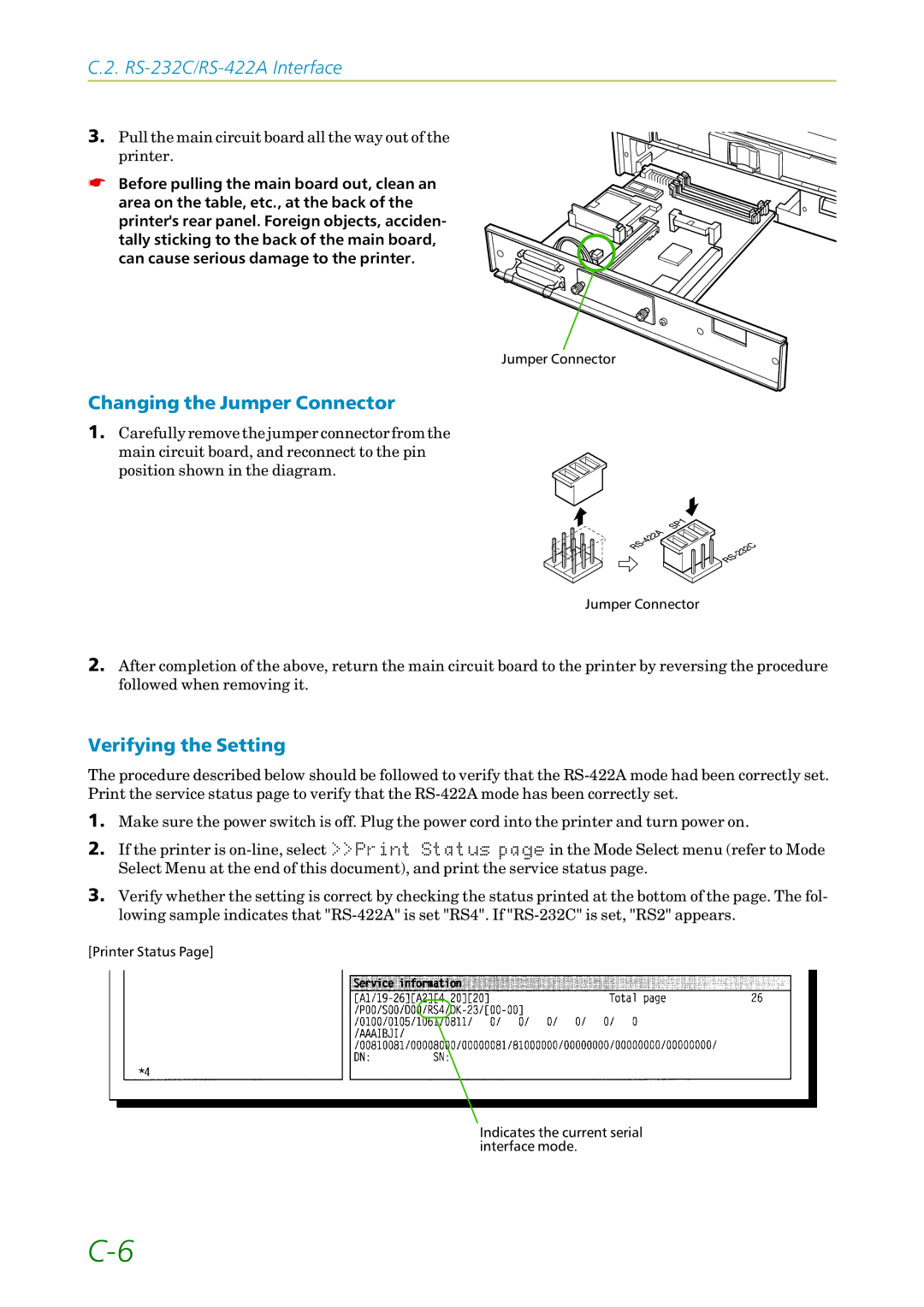
1.Carefully remove the jumper connector from the main circuit board, and reconnect to the pin
position shown in the diagram.
Jumper Connector
2.After completion of the above, return the main circuit board to the printer by reversing the procedure followed when removing it.
Verifying the Setting
The procedure described below should be followed to verify that the
1.Make sure the power switch is off. Plug the power cord into the printer and turn power on.
2.If the printer is
3.Verify whether the setting is correct by checking the status printed at the bottom of the page. The fol- lowing sample indicates that
[Printer Status Page]
Indicates the current serial interface mode.