User Guide
Lantronix Corporate Headquarters
Technical Support Sales Offices
Disclaimer
Table of Contents
Configuration via Telnet or Serial Port Setup Mode
Setup Mode Advanced Settings
Gpio Interface
List of Tables
List of Figures
Chapter Summary
Using This Guide
Purpose and Audience
Additional Documentation
XPico Integration Guide
Applications
Introduction
Capabilities
Configuration Methods
Protocol Support
Addresses and Port Numbers
Hardware Address
Port Numbers
Product Information Label
IP Address
Using DeviceInstaller
Installing DeviceInstaller
To install DeviceInstaller
Assigning an IP Address
Accessing the xPico Using DeviceInstaller
To view the units current settings
Select Assign a specific IP address and click Next
Name
Dhcp Device Name
Group
Comments
Device Family
Firmware Upgradeable
Supports Configurable
Pins
Supports Http Setup
Configuration Using Web Manager
Accessing Web-Manager Using DeviceInstaller
Network Configuration
Web-Manager Login Window
Select Obtain IP address automatically
Network Mode
To assign an IP address automatically
Static IP Address Configuration
Ethernet Configuration
Select Use the following IP configuration
To assign an IP address manually
To configure the xPico’s device server settings
Auto Negotiate
Advanced
Host List Configuration
Server Configuration
Channel 1 and 2 Configuration
Retry Settings
To configure the xPico’s host list
Host Information
Serial Settings
Port Settings
To configure the channel’s serial settings
Channel
Pack Control
Flush Input Buffer Serial to Network
Connection Settings TCP
To configure a channel’s TCP settings
Flush Output Buffer Network to Serial
At Time of Disconnect
TCP Connection Settings
Connect Mode Passive Connection
Connect Mode Active Connection
Endpoint Configuration
Connect Protocol
To configure a channel’s UDP settings
Connection Settings UDP
Disconnect Mode
Datagram Mode
Datagram Type
Use Broadcast
Device Address Table
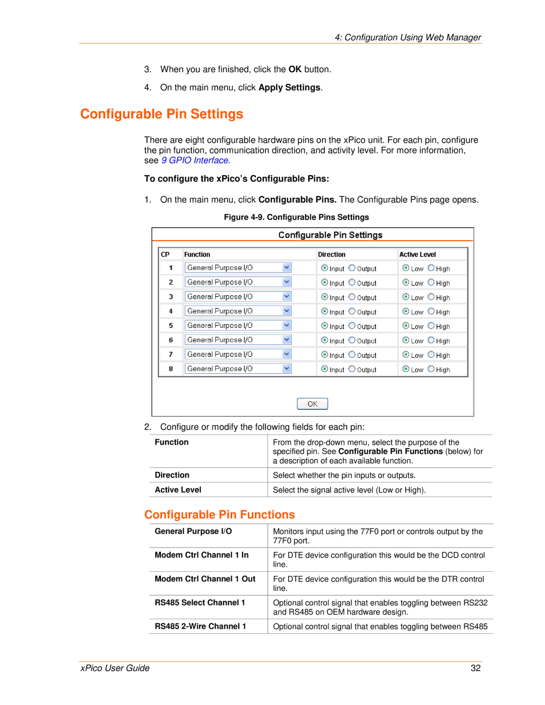
To configure the xPico’s Configurable Pins
Configurable Pin Settings
Configurable Pin Functions
Apply Settings
Apply Defaults
Serial Channel 1 Status LED
Serial Channel 2 Status LED
Telnet Connection
Configuration via Telnet or Serial Port Setup Mode
Accessing Setup Mode
Serial Port Connection
To establish a Telnet connection
Exiting Setup Mode
To exit setup mode
Setup Mode Server Configuration
Server Configuration Option
BootP/DHCP/AutoIP Options
IP Address
Change Telnet/Web-Manager Password
Set Gateway IP Address
Netmask Number of Bits for Host Part
Set DNS Server IP Address
Dhcp Name
Baudrate
Setup Mode Channel Configuration
Channel 1 Option 1 or Channel 2 Option
Interface Mode
Interface Mode Options
RS232 Interface Mode Settings
Flow
Connect Mode
Port Number
Flow Control Options
Reserved Port Numbers
Connect Mode Options
Incoming Connection
Incoming Connection
Response
Response
Active Startup
Manual Connection
Manual Connection Address Example
To enable the hostlist
Hostlist Option
Directed UDP
Modem Mode
Datagram Type
Modem Mode Commands
Numeric Response
Auto Increment Source Port
Send the Escape Sequence +++ in Modem Mode
Show IP addr after Ring
Disconnect Mode Options
Remote IP Address
Flush Mode Buffer Flushing
Pack Control
Send Characters
Packing Interval
Trailing Characters
DisConnTime Inactivity Timeout
Channel Port Password
Send Characters
Telnet Terminal Type
TCP Keepalive time in seconds
Setup Mode Advanced Settings
Expert Settings Option
ARP Cache timeout in seconds
Disable Monitor Mode at bootup
CPU Performance
Http Port Number
Security Settings Option
TCP Re-Transmission Timeout
Enable alternate MAC
Ethernet Connection Type
Snmp Community Name
Disable Snmp
Disable Telnet Setup
Disable Tftp Firmware Upgrade
Disable Port 77FE Hex
Disable Web Server
Disable Web Setup
Enable Encryption
To configure AES encryption on the xPico
Default Settings Option
Enable Enhanced Password
Disable Port 77F0 Hex
Channel 1 and Channel 2 Configuration Defaults
Expert Settings Defaults
Security Settings Defaults
Hostlist retry timeout
Start character for serial channel
Gpio Interface
Configurable Pins
Features
Commands
Byte 0 Command Types
Control Protocol
Guidelines
Command 10h, Get Functions
Command 11h, Get Directions
Command 12h, Get Active Levels
Command 13h, Get Current States
Command 19h, Set Directions
Command 1Ah, Set Active Levels
Command 1Bh, Set States
Command details
Response details
Firmware Upgrades
Using Tftp Graphical User Interface
Obtaining Firmware Reloading Firmware
To download new firmware from a computer
Using Tftp Command Line Interface
Tftp Window
To recover firmware
Monitor Mode
Entering Monitor Mode Using the Serial Port
Entering Monitor Mode Using the Network Port
Monitor Mode Commands
Monitor Mode Commands
G0, G1, ....,Ge, Gf
S0, S1,...,Se, Sf
Example
Command Response Codes
Response Meaning
Troubleshooting
Problems and Error Messages
Caps Lock is not on
Lock on
Troubleshooting
Technical Support Europe, Middle East, and Africa
Technical Support
Technical Support US
Binary to Hexadecimal Conversions
Converting Binary to Hexadecimal
Conversion Table
Scientific Calculator
Binary to Hexadecimal Conversions
Compliance
RoHS Notice