Operating Manual · Bedienungsanleitung · Mode d’emploi
Leica DM1000 Leica DM1000 LED
Page
Operating Manual
Copyrights
Copyrights
Contents
Important Notes about this Manual
Important Notes about this Manual
→ p
Intended Purpose of the Microscope
Intended Purpose of the Microscope
Not suitable for examining potentially infectious specimens
Safety Notes
Safety Notes
General Safety Notes
Microscope
Disposal
Overview of the Instrument
Specification Leica DM1000/DM1000 LED Condenser
Focusing
Overview of the Instrument
Overview of the Instrument
Installation Location
Unpacking the Microscope
Unpacking the Microscope
→ p , for additional instructions
Unpacking the Microscope Transport
Assembly
This case, read Chapter Optional Accessories → p
Assembling the Microscope
Specimen Holder
Assembly Adjusting the Focus Stop
Stage Lock
Assembly Condenser
Condenser holder Guiding notch
Assembly Tube and Eyepieces
Objectives
Assembly Light Source for the Transmitted Light Axis
Replacing the Lamp of the Integrated
Illumination
2 106z Lamp Housing
Hg and Xe lamps are powered by separate supply units
Install the burner in reverse order
Type
Hg 50 Burner
Xe 75 Burner
Connect the lamp housing to the external power supply
Hg 50a Hg 100c
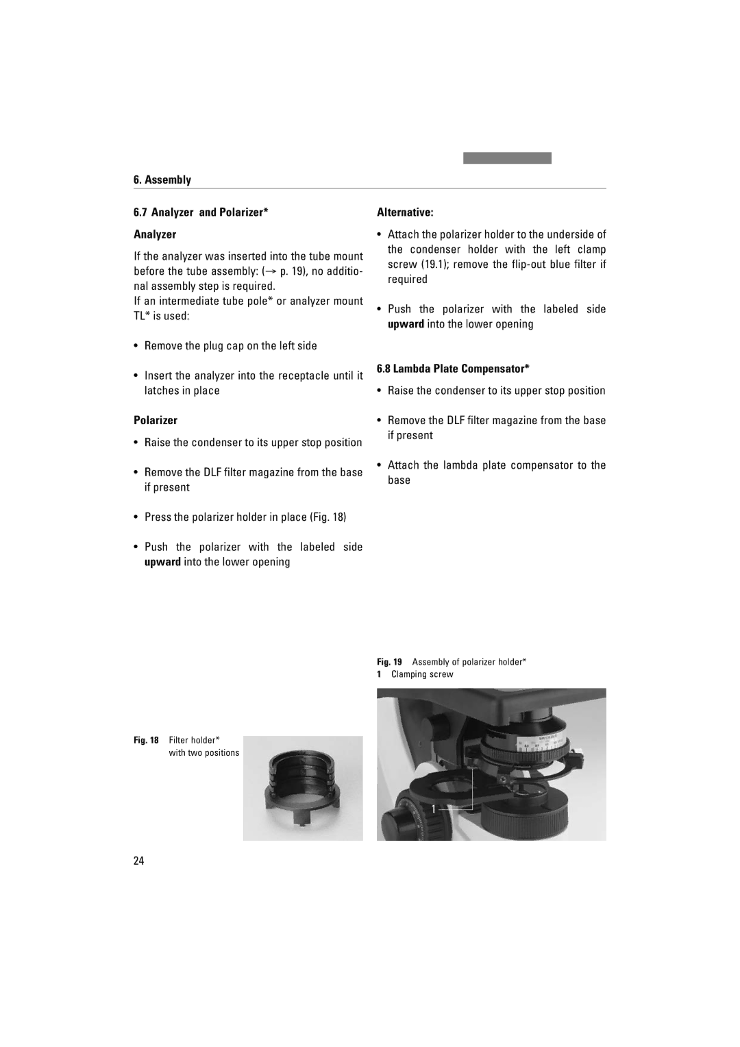
Assembly Analyzer and Polarizer* Analyzer
Alternative
Polarizer
Lambda Plate Compensator
Assembly Optional Accessories Camera
Mount, 0.32-1.6 x HC
Mount ENG, 0.5-2.4 x HC 1/2-inch
+ from zoom factor 0.42 x only
Assembly Ergomodule
Ergolift
Magnification Changer
Viewing Attachments
Connection to the Power Supply
Bottom of stand DM1000 LED Lid of the battery compartment
Switching on the Microscope
Switch on the microscope with the on/off switch
Start-up
Start-up
Checking Phase Contrast Rings
Focus on the specimen with the focus wheel
Start-up Adjusting the Light Sources
Never look directly into the beam path
Start-up Centering the Hg 50 W* Mercury Lamp
Direct arc image focused but decentered
Start-up
Start-up
Switching on
Torque Adjustment
Adjusting the Travel Range of the Stage
Operation
Focusing Coarse and Fine Focusing
Height Adjustment of the Focusing Wheels
Readjust the condenser
Operation Right-/Left-hand Operation
Adjusting the Viewing Distance
Adjusting the Viewing Angle
Adjusting the Eyepiece Section to the Arm Length
Operation Tubes
Correction for Vision Problems
Eyepieces
Eyepieces with Inlaid Reticle
Do not use the focus dial
Immersion objective released
Fluorescence Aperture Diaphragm
Fire Hazard
Supply unit
Operation Color-coded Condenser
Field diaphragm
Contrast Methods
Contrast Methods Brightfield
Contrast Methods Phase Contrast
Use the light ring slide
Darkfield
DF condenser
Contrast Methods Oblique Illumination
Polarization
Fluorescence
Measurements with the Microscope
Measurements with the Microscope
Linear Measurements
Micrometer Value
Measurements with the Microscope Thickness Measurements
Object Marker
Procedure
Rotate the lambda plate compensator out of light path fig
Swing in the lambda plate again
Identification of gout
Trouble shooting
Trouble shooting
Problem Cause/Remedy Stand
Trouble shooting Problem Cause/Remedy
Focus
Trouble shooting Problem Cause/Remedy Phase Contrast
Fluorescence is too weak
Cleaning
Cleaning Coated Parts
Care of the Microscope
Care of the Microscope
Cleaning glass surfaces and objectives
Or contact our Technical Service with any questions
Removing Immersion Oil
Handling Acids and Bases
Essential Wear and Spare Parts
Essential Wear and Spare Parts
Retrofitting Components
Retrofitting Components
Equipping the Condenser Disk
Condenser UCL/UCLP
Condenser UCA/P
Index
Index
EC Declaration of Conformity
EC Declaration of Conformity
Download
Bedienungsanleitung
Copyrights
Inhalt
Textsymbole, Piktogramme und ihre Bedeutung → S
Wichtige Hinweise zur Anleitung
Wichtige Hinweise zur Anleitung
Achtung
Zweckbestimmung des Mikroskops
Zweckbestimmung des Mikroskops
Sicherheitshinweise
Sicherheitshinweise
Allgemeine Sicherheitshinweise
Technische Daten des externen Netzteils
Entsorgung
Hinweis
Geräteübersicht
Fokussierung
Geräteübersicht
Geräteübersicht
Auspacken
Auspacken
Aufstellungsort
Auspacken Transport
Montage des Mikroskops
Montage
Objekttisch Achtung
Präparatehalter
Montage Fokusschwelle einstellen
Ziehen Sie die Schraube wieder fest
Tischfixierung
Montage Kondensor
Montage Tubus und Okulare Hinweis
Objektive
Montage Lichtquelle für die Durchlichtachse Achtung Hinweis
Werden
Die Durchlichtbeleuchtung mit Niedervolt
Ziehen Sie den Einschub 12.2 heraus
Lampenhaus 106z Achtung
Typ
Achtung Hg 50-Brenner
Xe 75-Brenner
Xe 75b Hg 100c
Schließen Sie das Lampenhaus am Vorschalt- gerät an
Montage Analysator und Polarisator* Analysator
Alternativ
Lambda-Plattenkompensator
Drehen Sie den Kondensor bis zum oberen Anschlag hoch
Montage Optionales Zubehör Kamera
Schrauben Sie die Kamera auf
Mount-Adapter 1 Mount-Adapter 1.25 17,5 Mount-Adapter 1,25
Montage Ergomodul
Vergrößerungswechsler
Diskussionseinrichtungen
Zeicheneinrichtung
Anschluss an die Stromversorgung
Einsetzen der Akkus nur bei DM1000 LED
Inbetriebnahme
Inbetriebnahme
Einschalten
Schalten Sie das Mikroskop am Ein-/Aus- schalter 24.1 ein
Phasenkontrastringe überprüfen
Fokussieren Sie das Präparat mit dem Fokus- handrad
Inbetriebnahme Justieren der Lichtquellen
Nie in den direkten Strahlengang blicken
Zentrieren der Quecksilberlampe Hg 50 W
Inbetriebnahme
Inbetriebnahme Achtung
Bedienung
Bedienung
Schalten Sie das Mikroskop am Ein/Aus-Schal- ter 37.1 ein
Einstellen der Gängigkeit Drehmoment
Bedienung Rechts-/Linksbedienung
Fokussierung Grob- und Feinfokussierung
Höhenverstellung der Fokusknöpfe
Fokussieren Sie das Bild wieder
Bedienung Tuben
Augenabstand einstellen
Einblickwinkel einstellen
Strahlenteilung bei Fototuben
Tubus HC L 2TU
Schaltstange Beobachtung
Okulare Hinweis
Okulare mit eingelegter Strichplatte
Sicherheitsdatenblatt zum Immersionsöl be- achten
Fluoreszenz Aperturblende
Brandgefahr
Bedienung Farbkodierter Kondensor
Leuchtfeldblende
Kontrastverfahren
Objektivvergrößerungen 1,6x und 2,5x
Kontrastverfahren Hellfeld
Schalten Sie die Kondensorscheibe* ggf. auf Position BF
Kontrastverfahren Phasenkontrast
Hinweise
Dunkelfeld DF Kondensor
Legen Sie ein Durchlichtpräparat auf
Kontrastverfahren Schiefe Beleuchtung
Polarisation
Falls vorhanden
Kondensor CLP/PH
Bringen Sie die Revolverscheibe in die Position λ oder λ /4
Fluoreszenz
Messungen mit dem Mikroskop
10.1 Längenmessungen
Mikrometerwert
Zur Ermittlung des Wertes gehen Sie folgendermaßen vor
Messungen mit dem Mikroskop Dickenmessungen
Beispiel
Objektmarkierer
Verfahrensweise
Schwenken Sie den Lambda-Plattenkompen- sator wieder ein
Gicht-Test Kristalle
Verfahren zur Bestimmung von Pseudogicht
Problembehandlung
Problem Ursache/Abhilfe Stativ
Beleuchtung
Problembehandlung Ursache/Abhilfe
Fokus
Dunkelfeld
Problem Ursache/Abhilfe Phasenkontrast
Es lässt sich kein Phasenkontrast einstellen
Objekttisch
Pflege des Mikroskops
Staubschutz Hinweis
Reinigung Achtung
Reinigen lackierter Teile
Entfernen von Immersionsöl Achtung
Umgang mit Säuren und Basen
Sicherungswechsel DM1000
WichtigsteVerschleiß-undErsatzteile
Wichtigste Verschleiß- und Ersatzteile
Nachrüstungen
Bestücken der Kondensorscheibe
Kondensor UCL/UCLP
Drehen Sie die Schraube 55.1 vollständig heraus
Nachrüstungen Achtung
Kondensor UCA/P
Höhenverstellung der Fokusknöpfe
EU-Konformitätserklärung
Mode d’emploi
Droits d’auteur
Droits d’auteur
Sommaire
Sommaire
Principales pièces d’usure
Remarques importantes concernant ce mode d’emploi
Remarques importantes concernant ce mode demploi
Fonction des microscopes
Fonction des microscopes
Consignes de sécurité
Elimination
Remarque
Vue d’ensemble
Mise au point
Vue densemble
Vue densemble
Lieu dinstallation
Déballage
Déballage
Déballage Transport
Platine Levier de commande x-y de la platine Remarque
Assemblage du microscope
Assemblage
Support de préparation
Desserrer le bouton de butée sur le gauche du microscope
Resserrer la vis de butée
Blocage des platines
Assemblage Condenseur
Dans le condenseur
Assemblage Tube et oculaires Remarque
Objectifs
Le service technique
Par LED intégré. La durée de vie de la diode
Dans ce
Leica DM1000 avec
Illuminateur à fluorescence
2 Boîtier de lampe 106z
Brûleur Hg
Brûleur Xe75
Xe 75b Hg 50a Hg 100c
Raccorder le boîtier de lampe au régulateur de puissance
Assemblage Analyseur et polariseur Analyseur
Polariseur
Autre méthode
Compensateur à lame Lambda
Assemblage Accessoires en option Caméra
Indispensable dans chacun des cas optique TV 0.5 x HC
Assemblage Module ergonomique
Dispositif de rehausse ergonomique
Changeur de grossissement
Dispositifs de discussion
Connexion au bloc dalimentation
Dessous du statif DM1000 LED Compartiment à batteries ouvert
Mise en service
Mise en service
Éclairage de Köhler
Mise sous tension
Vérification des anneaux de contraste de phase
Éclairage de Köhler
Clef de centrage
Mise en service Ajustement des sources de lumière
Centrage de la lampe au mercure Hg 50 W
Mise en service
Mise en service
Réglage de la plage de déplacement de la platine
Utilisation
Utilisation
Réglage de la direction du pas couple de rota- tion
Utilisation Utilisation à droite/gauche
Mise au point Mise au point grossière et fine
Réglage en hauteur des boutons de mise au point
Utilisation Tubes Remarque
Réglage de la distance interoculaire
Réglage de langle dobservation
Adapter lextension doculaire à la longueur de bras
Oculaires Remarque
Oculaires avec réticule
Correction de vision déficiente
Respecter la fiche de sécurité relative à lhuile dimmersion
Objectif à immersion, déverrouillé
Utilisation Sources de lumière Diascopie
Régler la luminosité avec le bouton de réglage
Mettre sous tension la lampe du régulateur de puissance
Diaphragme douverture
Utilisation Condenseur avec repères en couleur
Une aptitude au fond noir Une modification du contraste
Diaphragme de champ
Méthodes de contraste
Méthodes de contraste
Grandissements dobjectifs 1.6x et
Basculer la tête de condenseur hors du tra- jet optique
Méthodes de contraste Contraste de phase
APL. ACHR.0.9 P Utiliser le coulisseau à anneaux de lumière
Insérer le coulisseau à anneaux de lumière DF jusquen butée
Remarques
4 Éclairage oblique
Tube intermédiaire Pol* Mettre lanalyseur en place
Si existante
Mesures avec le microscope
Mesures avec le microscope
Mesures de longueur
Valeur en micromètres
Mesures avec le microscope Mesures dépaisseur
Exemple
Marqueur dobjet
Différenciation de la goutte et de la pseudo-goutte
Assemblage → p
Faire sortir la lame Lambda du trajet optique fig
Procédure
Levier vers la gauche
Levier Vers la droite Test de la pseudo-goutte
Levier Vers la droite
Problème Cause/Solution Statif
11. Dépannage
11. Dépannage
Éclairage
11. Dépannage Problème Cause/Solution
Fond noir
Il nest pas possible de régler le contraste de polarisation
11. Dépannage Problème Cause/Solution Contraste de phase
Platine
Entretien du microscope
Entretien du microscope
Pare-poussière Remarque
Nettoyage
Maniement des acides et bases
Changement de fusible DM1000
Principales pièces d’usure et de rechange
Principales pièces dusure et de rechange
Adaptations ultérieures
Adaptations ultérieures
14.1 Équipement de la tourelle de condenseur Remarques
Condenseur UCL/UCLP
Condenseur UCA/P
DIC
Goutte/Pseudo-goutte 49 Grossissement de lobjectif 2.5x
16. Déclaration de conformité UE
16. Déclaration de conformité UE