Return to Section TOC
Return to Section TOC
Return to Master TOC
Return to Master TOC
THEORY OF OPERATION
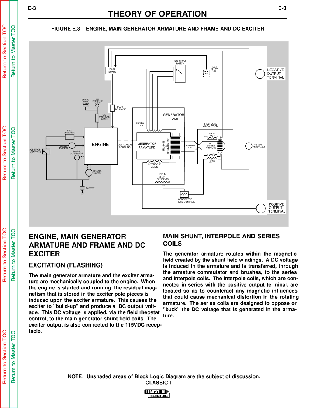
FIGURE E.3 – ENGINE, MAIN GENERATOR ARMATURE AND FRAME AND DC EXCITER
|
|
|
|
|
|
| SELECTOR |
|
|
|
|
|
|
|
|
| SWITCH |
|
|
|
|
|
|
|
|
|
| REED |
|
|
| IDLER |
|
|
|
|
| RELAY | NEGATIVE |
|
| BOARD |
|
|
|
|
| CR2 | |
|
|
|
|
|
|
|
| OUTPUT | |
|
|
|
|
|
|
|
|
| |
|
|
|
|
|
|
|
|
| TERMINAL |
| ENGINE | OIL |
|
|
|
|
|
|
|
| HOUR | PRESSURE |
|
|
|
|
|
|
|
| METER | LIGHT |
|
|
|
|
|
|
|
|
|
| IDLER |
|
|
|
|
|
|
|
| SOLENOID |
|
|
|
|
|
| |
|
| OIL |
|
| GENERATOR |
|
| ||
|
| PRESSURE |
|
|
| FRAME |
|
| |
|
| SWITCH |
|
|
|
|
| ||
|
|
|
| SERIES |
|
|
| RESIDUAL |
|
|
|
|
| COILS |
|
|
|
| |
|
|
|
|
|
|
| MAGNETISM |
| |
| FUEL |
|
|
|
|
|
|
|
|
| SHUTDOWN |
|
|
|
|
|
| SHUNT |
|
|
|
|
|
| BRUSHES & | COMMUTATOR |
| FIELD |
|
SWITCH |
| ENGINE | MECHANICAL | GENERATOR | ARMATURE | EXCITER | 115 VDC | ||
|
|
|
|
|
|
|
| DC |
|
| ENGINE |
| COUPLING | ARMATURE |
|
| SHAFT | ARMATURE | RECEPTACLE |
IGNITION | IGNITION |
|
|
| |||||
ENGINE |
|
|
|
|
|
|
|
| |
|
|
|
|
|
|
|
|
| |
| ALTERNATOR |
|
|
|
|
|
|
|
|
|
|
|
|
|
|
|
| SERIES |
|
|
|
|
| INTERPOLE |
|
| FIELD |
| |
|
|
|
|
|
|
|
| ||
|
|
|
| COILS |
|
|
|
| |
|
| STARTER |
|
|
|
|
|
|
|
|
| MOTOR |
|
| FIELD |
|
|
|
|
|
|
|
|
|
|
|
|
| |
|
|
|
|
| SHUNT |
|
|
|
|
|
|
|
|
| WINDINGS |
|
|
| |
| BATTERY |
|
|
|
|
|
|
| |
|
|
|
|
|
|
| GENERATOR |
|
|
|
|
|
|
|
|
| FIELD CONTROL |
| POSITIVE |
|
|
|
|
|
|
|
|
| |
|
|
|
|
|
|
|
|
| OUTPUT |
|
|
|
|
|
|
|
|
| TERMINAL |
Return to Section TOC
to Section TOC
Return to Master TOC
to Master TOC
ENGINE, MAIN GENERATOR ARMATURE AND FRAME AND DC EXCITER
EXCITATION (FLASHING)
The main generator armature and the exciter arma- ture are mechanically coupled to the engine. When the engine is started and running, the residual mag- netism that is stored in the exciter pole pieces is induced upon the exciter armature. This causes the exciter to
MAIN SHUNT, INTERPOLE AND SERIES COILS
The generator armature rotates within the magnetic field created by the shunt field windings. A DC voltage is induced in the armature and is transferred, through the armature commutator and brushes, to the series and interpole coils. The interpole coils, which are con- nected in series with the positive output terminal, are located so as to counteract any magnetic influences that could cause mechanical distortion in the rotating armature. The series coils are designed to oppose or "buck" the DC voltage that is generated in the arma- ture.
Return
Return
NOTE: Unshaded areas of Block Logic Diagram are the subject of discussion.