TROUBLESHOOTING & REPAIR
TOC | TOC |
| MAIN GENERATOR FRAME REMOVAL | ||
Section | Master |
| AND REPLACEMENT (continued) | ||
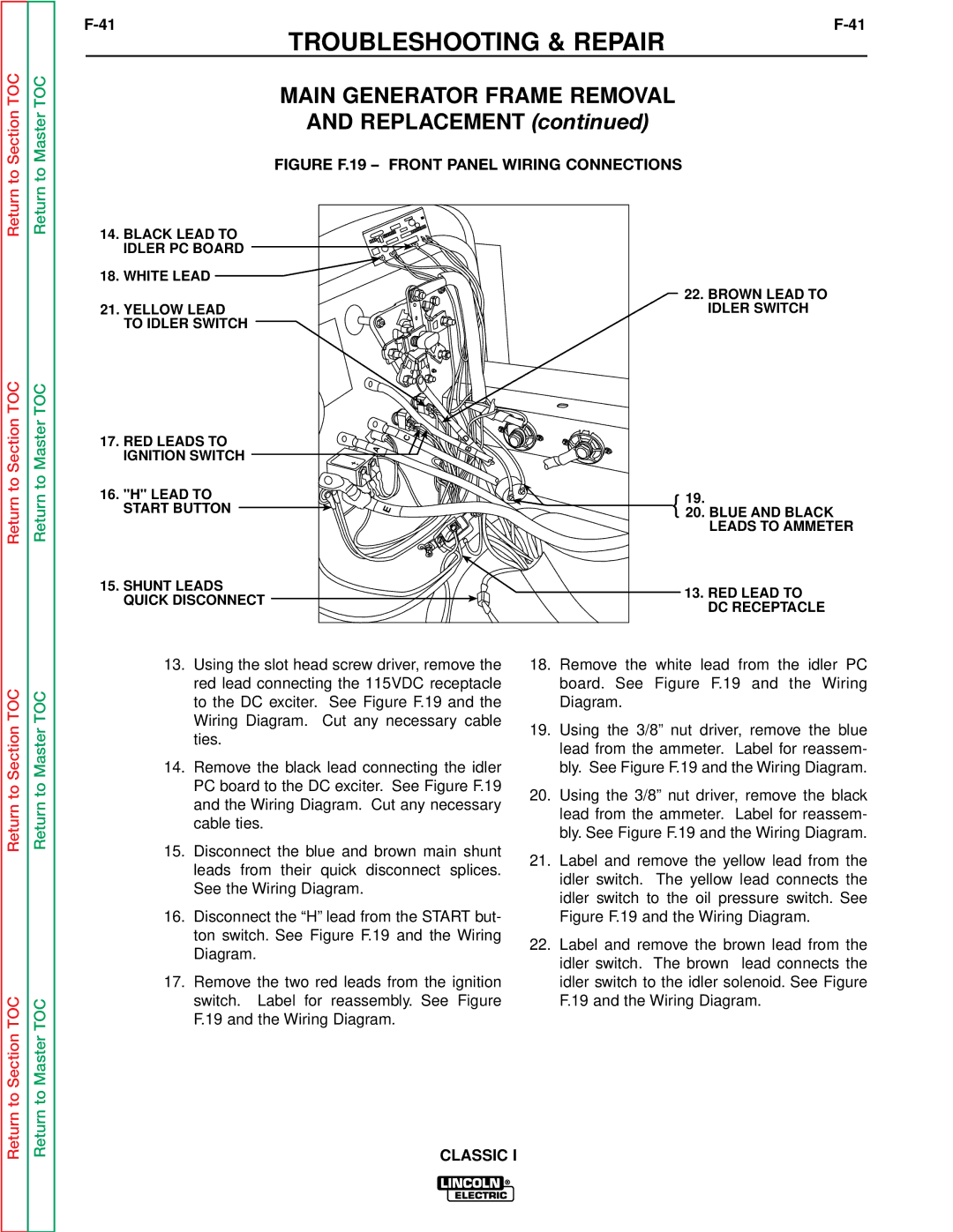
| FIGURE F.19 – FRONT PANEL WIRING CONNECTIONS | ||||
Return to | Return to |
| |||
14. BLACK LEAD TO |
|
| |||
|
|
|
| ||
|
| IDLER PC BOARD |
|
| |
|
| 18. WHITE LEAD |
|
| |
|
|
|
| 22. BROWN LEAD TO | |
|
| 21. YELLOW LEAD |
| IDLER SWITCH | |
|
| TO IDLER SWITCH |
|
| |
TOC | TOC |
|
|
| |
to Section | to Master | 17. RED LEADS TO | C | D | |
A | B | ||||
IGNITION SWITCH | |||||
|
| ||||
16. "H" LEAD TO |
| { 20.19. BLUE AND BLACK | |||
Return | Return |
| |||
START BUTTON | E | ||||
|
| LEADS TO AMMETER | |||
|
|
| |||
|
| 15. SHUNT LEADS |
| 13. RED LEAD TO | |
|
| QUICK DISCONNECT |
| ||
|
|
| DC RECEPTACLE | ||
|
|
|
| ||
|
| 13. | Using the slot head screw driver, remove the | 18. Remove the white lead from the idler PC | |
TOC | TOC |
| red lead connecting the 115VDC receptacle |
| board. See Figure F.19 and the Wiring |
| to the DC exciter. See Figure F.19 and the |
| Diagram. | ||
|
|
|
| ||
Section | Master |
| Wiring Diagram. Cut any necessary cable | 19. | Using the 3/8” nut driver, remove the blue |
| ties. | ||||
|
| lead from the ammeter. Label for reassem- | |||
|
|
|
| ||
|
|
|
|
| |
|
| 14. | Remove the black lead connecting the idler |
| bly. See Figure F.19 and the Wiring Diagram. |
to | to |
| PC board to the DC exciter. See Figure F.19 | 20. | Using the 3/8” nut driver, remove the black |
| and the Wiring Diagram. Cut any necessary | ||||
Return | Return |
| |||
|
| lead from the ammeter. Label for reassem- | |||
| cable ties. |
| |||
|
|
|
| ||
|
|
|
| bly. See Figure F.19 and the Wiring Diagram. | |
|
|
|
|
| |
|
| 15. Disconnect the blue and brown main shunt | 21. Label and remove the yellow lead from the | ||
|
|
| leads from their quick disconnect splices. | ||
|
|
|
| idler switch. The yellow lead connects the | |
|
|
| See the Wiring Diagram. |
| |
|
|
|
| idler switch to the oil pressure switch. See | |
|
|
|
|
| |
|
| 16. Disconnect the “H” lead from the START but- |
| Figure F.19 and the Wiring Diagram. | |
|
|
| ton switch. See Figure F.19 and the Wiring | 22. Label and remove the brown lead from the | |
|
|
| Diagram. | ||
|
|
|
| idler switch. The brown lead connects the | |
|
|
|
|
| |
|
| 17. | Remove the two red leads from the ignition |
| idler switch to the idler solenoid. See Figure |
Return to Section TOC | Return to Master TOC |
| switch. Label for reassembly. See Figure |
| F.19 and the Wiring Diagram. |
| F.19 and the Wiring Diagram. |
|
| ||
| CLASSIC I |
|
| ||
|
|
|
|
| |
