Return to Section TOC
Return to Section TOC
Return to Master TOC
Return to Master TOC
TROUBLESHOOTING & REPAIR
DC EXCITER ARMATURE AND FIELD COILS
REMOVAL AND REPLACEMENT (continued)
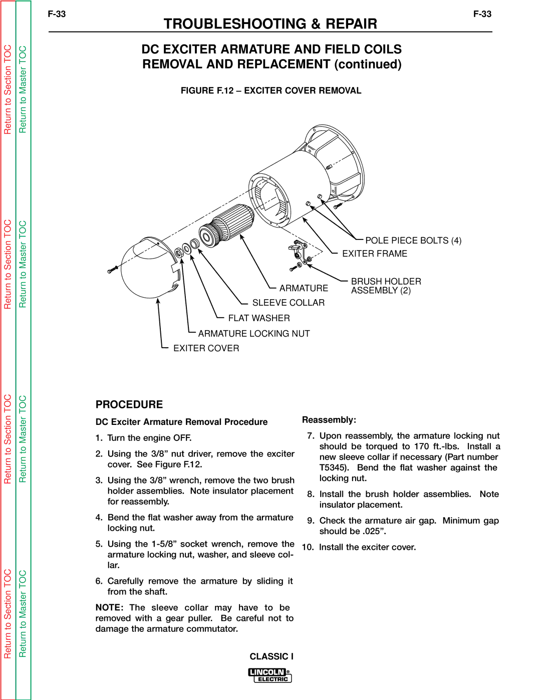
FIGURE F.12 – EXCITER COVER REMOVAL
| POLE PIECE BOLTS (4) |
| EXITER FRAME |
ARMATURE | BRUSH HOLDER |
ASSEMBLY (2) | |
SLEEVE COLLAR |
|
FLAT WASHER |
|
ARMATURE LOCKING NUT |
|
EXITER COVER |
|
Return to Section TOC
Return to Section TOC
Return to Master TOC
Return to Master TOC
PROCEDURE
DC Exciter Armature Removal Procedure
1.Turn the engine OFF.
2.Using the 3/8” nut driver, remove the exciter cover. See Figure F.12.
3.Using the 3/8” wrench, remove the two brush holder assemblies. Note insulator placement for reassembly.
4.Bend the flat washer away from the armature locking nut.
5.Using the
6.Carefully remove the armature by sliding it from the shaft.
NOTE: The sleeve collar may have to be removed with a gear puller. Be careful not to damage the armature commutator.
Reassembly:
7.Upon reassembly, the armature locking nut should be torqued to 170
8.Install the brush holder assemblies. Note insulator placement.
9.Check the armature air gap. Minimum gap should be .025”.
10.Install the exciter cover.