OPERATION
Return to Section TOC
TO USE THE CLASSIC I FOR DC WIRE FEED WELDING (CONSTANT VOLTAGE) WITH WIRE FEED MODULE:
1.Connect the
2.Set the wire feeder and Classic I for CV operation.
3.Start the engine. See Engine Operation in this section of the manual.
4.Set the Idler Switch to "AUTO."
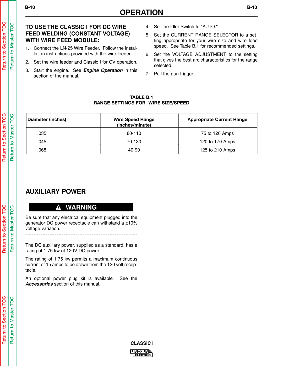
5.Set the CURRENT RANGE SELECTOR to a set- ting appropriate for your wire size and wire feed speed. See Table B.1 for recommended settings.
6.Set the VOLTAGE ADJUSTMENT to the setting that gives the best arc characteristics for the range selected.
7.Pull the gun trigger.
Return to Section TOC
Return to Section TOC
Return to Section TOC
Return to Master TOC
Return to Master TOC
Return to Master TOC
Return to Master TOC
TABLE B.1
RANGE SETTINGS FOR WIRE SIZE/SPEED
Diameter (inches) | Wire Speed Range | Appropriate Current Range |
|
| (inches/minute) |
|
|
.035 | 75 to 120 Amps |
| |
.045 | 120 to 170 Amps |
| |
.068 | 125 to 210 Amps |
| |
|
|
|
|
AUXILIARY POWER
WARNING
Be sure that any electrical equipment plugged into the generator DC power receptacle can withstand a ±10% voltage variation.
The DC auxiliary power, supplied as a standard, has a rating of 1.75 kw of 120V DC power.
The rating of 1.75 kw permits a maximum continuous current of 15 amps to be drawn from the 120 volt recep- tacle.
An optional power plug kit is available. See the
Accessories section of this manual.
