Return to Section TOC
Return to Section TOC
Return to Master TOC
Return to Master TOC
TROUBLESHOOTING & REPAIR
DC EXCITER TEST (continued)
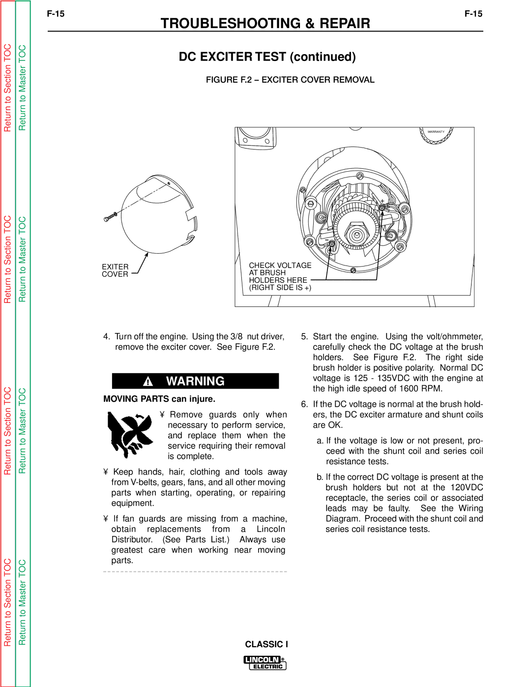
FIGURE F.2 – EXCITER COVER REMOVAL
| WARRANTY |
| + |
EXITER | CHECK VOLTAGE |
COVER | AT BRUSH |
| HOLDERS HERE |
| (RIGHT SIDE IS +) |
Return to Section TOC
Return to Section TOC
Return to Master TOC
Return to Master TOC
4.Turn off the engine. Using the 3/8” nut driver, remove the exciter cover. See Figure F.2.
WARNING
MOVING PARTS can injure.
•Remove guards only when necessary to perform service, and replace them when the service requiring their removal is complete.
•Keep hands, hair, clothing and tools away from
•If fan guards are missing from a machine, obtain replacements from a Lincoln Distributor. (See Parts List.) Always use greatest care when working near moving parts.
5.Start the engine. Using the volt/ohmmeter, carefully check the DC voltage at the brush holders. See Figure F.2. The right side brush holder is positive polarity. Normal DC voltage is 125 - 135VDC with the engine at the high idle speed of 1600 RPM.
6.If the DC voltage is normal at the brush hold- ers, the DC exciter armature and shunt coils are OK.
a.If the voltage is low or not present, pro- ceed with the shunt coil and series coil resistance tests.
b.If the correct DC voltage is present at the brush holders but not at the 120VDC receptacle, the series coil or associated leads may be faulty. See the Wiring Diagram. Proceed with the shunt coil and series coil resistance tests.