Return to Section TOC
Return to Section TOC
Return to Master TOC
Return to Master TOC
TROUBLESHOOTING & REPAIR
DC EXCITER TEST (continued)
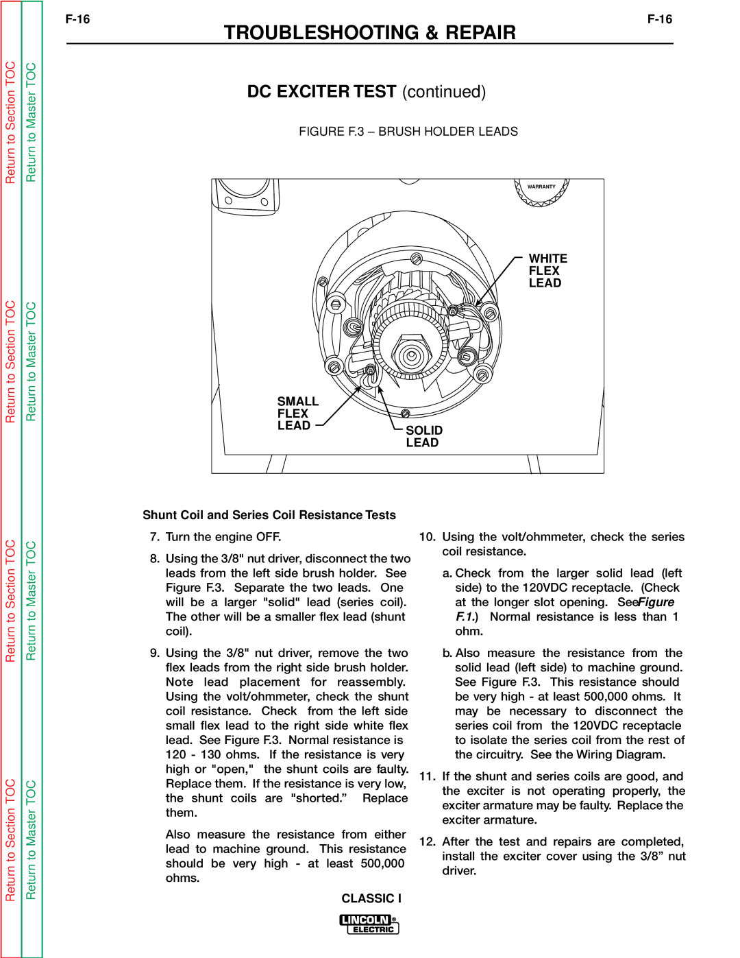
FIGURE F.3 – BRUSH HOLDER LEADS
| WARRANTY |
| WHITE |
| FLEX |
| LEAD |
SMALL |
|
FLEX |
|
LEAD | SOLID |
| |
| LEAD |
Return to Section TOC
Return to Section TOC
Return to Master TOC
Return to Master TOC
Shunt Coil and Series Coil Resistance Tests
7.Turn the engine OFF.
8.Using the 3/8" nut driver, disconnect the two leads from the left side brush holder. See Figure F.3. Separate the two leads. One will be a larger "solid" lead (series coil). The other will be a smaller flex lead (shunt coil).
9.Using the 3/8" nut driver, remove the two flex leads from the right side brush holder. Note lead placement for reassembly. Using the volt/ohmmeter, check the shunt coil resistance. Check from the left side small flex lead to the right side white flex lead. See Figure F.3. Normal resistance is 120 - 130 ohms. If the resistance is very high or "open," the shunt coils are faulty. Replace them. If the resistance is very low, the shunt coils are "shorted.” Replace them.
Also measure the resistance from either lead to machine ground. This resistance should be very high - at least 500,000 ohms.
CLASSIC I
10.Using the volt/ohmmeter, check the series coil resistance.
a.Check from the larger solid lead (left side) to the 120VDC receptacle. (Check at the longer slot opening. See Figure F.1.) Normal resistance is less than 1 ohm.
b.Also measure the resistance from the solid lead (left side) to machine ground. See Figure F.3. This resistance should be very high - at least 500,000 ohms. It may be necessary to disconnect the series coil from the 120VDC receptacle to isolate the series coil from the rest of the circuitry. See the Wiring Diagram.
11.If the shunt and series coils are good, and the exciter is not operating properly, the exciter armature may be faulty. Replace the exciter armature.
12.After the test and repairs are completed, install the exciter cover using the 3/8” nut driver.
