INSTALLATION
Return to Section TOC
Section TOC
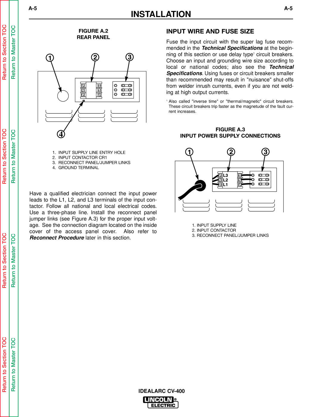
FIGURE A.2
REAR PANEL
INPUT WIRE AND FUSE SIZE
Fuse the input circuit with the super lag fuse recom- mended in the Technical Specifications at the begin- ning of this section or use delay type1 circuit breakers. Choose an input and grounding wire size according to local or national codes; also see the Technical Specifications. Using fuses or circuit breakers smaller than recommended may result in "nuisance"
1Also called "inverse time" or "thermal/magnetic" circuit breakers. These circuit breakers trip faster as the magnetude of the fault cur- rent increases.
FIGURE A.3
INPUT POWER SUPPLY CONNECTIONS
1.INPUT SUPPLY LINE ENTRY HOLE
2.INPUT CONTACTOR CR1
3.RECONNECT PANEL/JUMPER LINKS
4.GROUND TERMINAL
Return to Section TOC
Return to Master TOC
Return to Master TOC
Return to Master TOC
Have a qualified electrician connect the input power leads to the L1, L2, and L3 terminals of the input con- tactor. Follow all national and local electrical codes. Use a
1.INPUT SUPPLY LINE
2.INPUT CONTACTOR
3.RECONNECT PANEL/JUMPER LINKS
Return to Section TOC
Return to Master TOC
IDEALARC