Return to Section TOC
Return to Section TOC
Return to Section TOC
Return to Section TOC
Return to Master TOC
Return to Master TOC
Return to Master TOC
Return to Master TOC
TROUBLESHOOTING & REPAIR
MAIN TRANSFORMER REMOVAL & REPLACEMENT (continued)
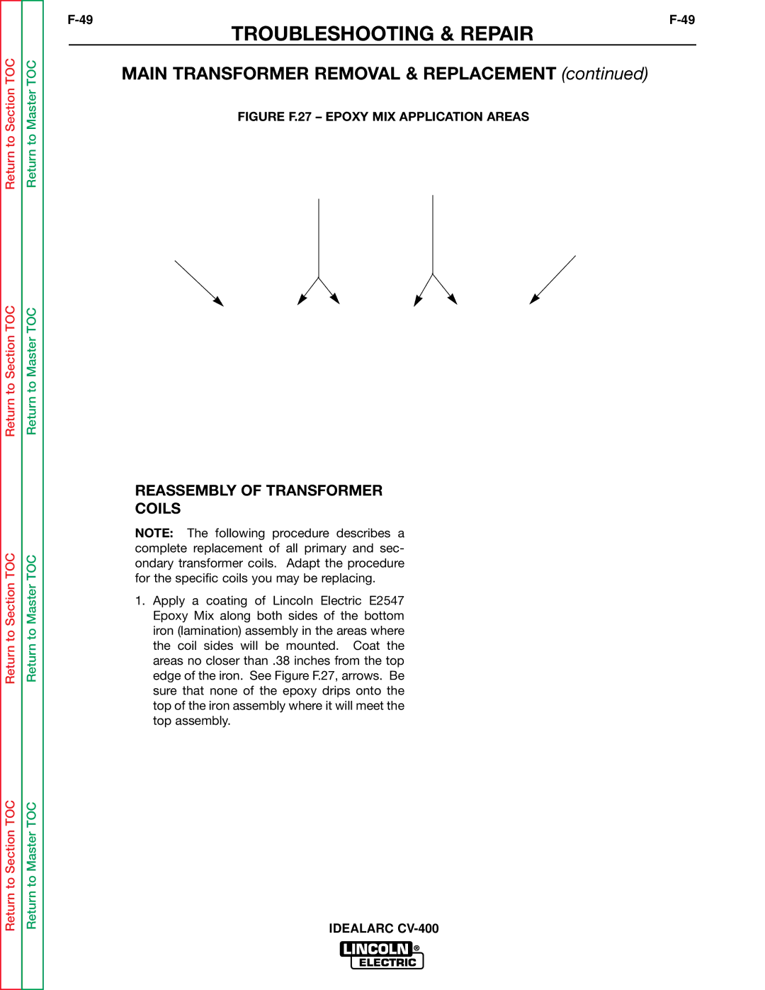
FIGURE F.27 – EPOXY MIX APPLICATION AREAS
REASSEMBLY OF TRANSFORMER
COILS
NOTE: The following procedure describes a complete replacement of all primary and sec- ondary transformer coils. Adapt the procedure for the specific coils you may be replacing.
1.Apply a coating of Lincoln Electric E2547 Epoxy Mix along both sides of the bottom iron (lamination) assembly in the areas where the coil sides will be mounted. Coat the areas no closer than .38 inches from the top edge of the iron. See Figure F.27, arrows. Be sure that none of the epoxy drips onto the top of the iron assembly where it will meet the top assembly.